BackStep Technique for Tig Welding Thin Metal
TIG welding thin metal demands a surgeon’s touch: tight control of heat input, steady hand movements, and a welding sequence that prevents the plate from becoming a warped pancake. The backstep technique is a proven method to limit longitudinal distortion in thin-sheet TIG welding, particularly in butt joints around 0.043 inches (≈1 mm) thick. This article explains the backstep method in depth, integrates practical setup and parameter guidance (including specific experimental settings), and shows how chill bars and fixturing choices affect results. The goal is to give a complete, actionable guide you can use in the shop.
Fundamentals of TIG Welding Thin Metal
TIG welding transfers heat very efficiently into a small area, which is excellent for control but makes thin materials sensitive to heat buildup. Thin carbon steel at ~0.043 in behaves differently than thicker plates: it reaches puddle temperature quickly, is prone to burn-through at too-high amperage, and will distort with uneven longitudinal heat input.
Key variables:
Heat input: A function of current, arc efficiency, and travel speed. Lower the input to prevent burn-through; raise it enough to wet out the joint and penetrate.
Travel speed: Faster travel reduces heat per unit length but also reduces penetration. For thin materials, travel speed and pedal modulation are your two most powerful controls.
Penetration: The weld should achieve fusion without excessive throat size. The rule of thumb discussed below helps estimate amperage needs.
The Backstep Technique — Theory and Benefits
What is backstepping?
Backstepping breaks a continuous weld into overlapping short segments laid out so thermal contraction pulls the plate toward already-cooled metal. Practically, you weld from the middle toward one end, stop, then start at the opposite end and weld back toward the middle — the beads meet and tie in. This creates a laddered thermal pattern rather than a continuous heat trail from start to finish.
How backstepping limits distortion
When you weld from one end to the other, the molten metal and heated zone cause shrinkage as it cools; that shrinkage is directional and tends to pull the workpiece lengthwise, which can produce a bow. Backstepping distributes shrinkage in two opposing directions and “locks” sections in place as they cool. Think of it like stitching: rather than sewing an entire seam in one direction (which bunches fabric), you stitch in small, alternating segments that hold fabric flat.
When to choose backstep vs. continuous welding
Backstepping excels on thin, long sections and butt joints where longitudinal distortion is critical. For very small welds, or when appearance demands a single continuous bead, continuous welding might be acceptable. However, when distortion control is a priority — for fixtures, thin panels, or assemblies needing tight tolerances — backstep is often the better choice.
Preparation and Fixturing for Backstep Welding
Joint design and fit-up for 1G square-groove butt joints
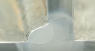
Maintain tight, consistent root gaps. With ~0.043 in material, your tolerance is small; too large a gap invites burn-through or an overly convex weld. Clean the joint surfaces of scale, oil, and paint. Use consistent edge preparation to ensure predictable penetration.
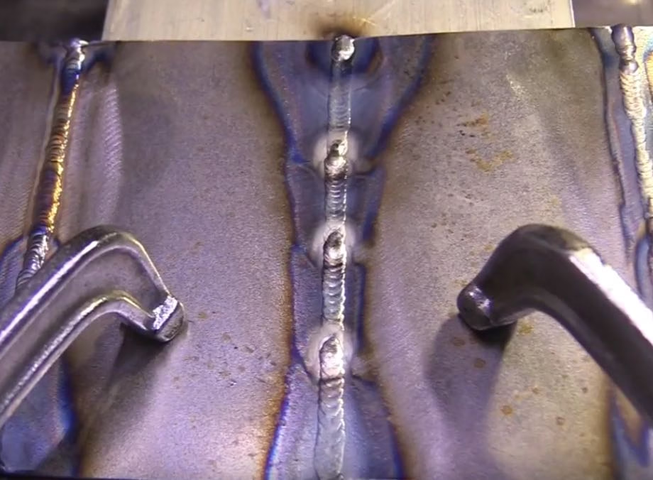
Tacking strategy — button tacks and why they help
Button tacks are slightly heavier tack welds at joint ends that act as anchors. When you start or stop a thin-sheet weld, the arc pressure can blow out edges or distort the metal locally. A small mound of filler at the ends acts like a buffer: the bead ties into something a little thicker and more robust, which prevents the arc from thinning the edge. Place extra small “button” tacks at both ends during tacking — they also serve as reliable start/stop reference points for the backstep sequence.
Clamping, spacing, and the role of a heatsink
Use a heavy backing plate (aluminium is excellent) as a heatsink to control local heat. Clamp the thin plates to a large aluminium plate to act as a heat sink and backing. If the heatsink is too aggressive from the start, it may over-chill the weld and demand much higher amperage; using spacer plates initially moderates that effect. Good fixturing pulls the plates flat and maintains root alignment while permitting heat to move into the backing where desirable.
Chill Bars and Heat Sinks
Purpose of chill bars
Chill bars (large metal backing or clamps) rapidly extract heat from the weld zone, reducing local expansion and shrinkage and therefore lowering distortion. They also provide a consistent thermal mass that can improve bead appearance by reducing oxidation and allowing better shielding.
How chill bars change amperage and travel speed
Because chill bars sink heat away quickly, you must increase amperage to maintain penetration — the user research showed a jump from ~55 A (with spacers) to ~70 A when the plates were clamped directly to the aluminum block. Increased amperage usually necessitates slower travel to maintain appropriate bead geometry and tie-in. In short: chill bars need higher power and slightly slower travel.
Using spacer plates to moderate chill
If you want the backing benefits without the full chilling effect, place thin spacers between the workpiece and the backing plate for the initial pass. This lets the first pass fuse without the immediate, heavy heat-sinking effect, and then you can clamp the work down for finishing passes if appropriate.
Practical Parameters and Equipment
Amperage rules of thumb (1 amp per 0.001 in) and adjustments
A helpful rule is 1 amp per 0.001 in of material thickness for full penetration on carbon steel. For 0.043 in material, that suggests about 43 amps as a baseline. Because TIG arc efficiency, joint fit-up, and chill bars change behaviour, practitioners often run a little higher. Stainless steel requires slightly lower amps; aluminium requires more.
Filler rod size, cup selection, and gas flow
A 0.045 in filler rod is a good match for thin carbon steel in many cases. Cup size affects gas coverage; These are sensible starting points: small cup, focused shielding, steady flow without turbulence. Adjust gas flow for the environment (wind, drafts) and ensure your cup-to-work distance is consistent.
Pedal control and the three-second puddle rule
The three-second puddle rule says the puddle should form within three seconds of arc initiation — if not, increase amperage. Pedal control gives you gradual power and is often superior to fixed current for thin work. Use the pedal to ramp up quickly to form the puddle, then regulate to maintain size and travel speed.
Step-by-Step Execution of a Backstep Weld
First pass — starting in the middle and moving to the end
Clamp work and ensure button tacks are in place at ends.
Start at the center of the joint. Initiate arc, form a controlled puddle within three seconds. Move toward one end using a steady travel speed and appropriate filler addition. Maintain a short arc length and consistent torch angle.
As you approach the button tack at the end, taper the pedal slowly and leave the filler rod in the puddle for a beat during the taper to avoid blowing out the thin edge.
Tapering, leaving the rod in the puddle, and preventing blowout
Slowly reducing amps while keeping the rod in the puddle gives the weld time to solidify in a controlled shape. This practice reduces crater formation and prevents the arc from ejecting molten metal at the thin end. Always avoid an abrupt shutoff.
Second pass — working from the opposite end back to the middle
Immediately after the first pass, start at the far button tack and weld toward the first bead. Overlap slightly when tying in. Use progressively less filler as you approach the previous bead to blend properly and avoid excessive reinforcement.
Overlap, tying beads, and crater management
Tying beads requires controlled overlap: enough to fuse to the first bead but not so much that you remelt it excessively. Gradually reduce filler and pedal to create a smooth tie-in and avoid crater cracks. Slow tapering is particularly important when welding steels prone to crater cracking (e.g., chromoly, some stainlesss).
Troubleshooting and Common Pitfalls
Lack of penetration vs. burn-through
If your bead lacks penetration, increase amperage slightly, slow travel, or ensure good fit-up. If you burn through, back off amperage, increase travel speed, or add a slight backing support to dissipate heat. Chill bars can help prevent local burn-through but require increased amperage — balance accordingly.
Crater cracks and slow taper solutions
Crater cracking occurs when a large volume of molten metal solidifies rapidly, especially on high-strength steels. Counter this with a slow pedal taper while holding the rod in place so the weld solidifies under compressive conditions and without sharp thermal gradients.
Weld appearance issues and porosity causes
Dull, oxidized beads often mean poor shielding; check gas flow, cup condition, and gas lens setup. Porosity is usually contamination (oil, rust, paint) or turbulent shielding gas. Clean parts thoroughly and reduce drafts or increase flow modestly.
Advanced Tips and Variations
Using backstep on stainless steel and aluminum — differences
Stainless: Lower amperage than carbon steel generally, slower cooling rates, and susceptibility to sensitization if overheated. Backstepping helps but beware of warping and interpass temperature. Use backing and spacing appropriately.
Aluminum: Much higher amp requirements for penetration and greater thermal conductivity. Chill bars and backstepping are still useful but expect different puddle behavior and the need for AC TIG settings and potentially pulse TIG to control heat.
Combining backstep with stitch welds or sequence welding
Large panels can benefit from stitch welding (short intermittent welds) combined with a backstep-like sequence — weld short segments in a planned pattern that minimizes continuous heat runs. Sequence welding across a panel (e.g., welding equidistant stitch welds) reduces overall distortion.
Minimizing distortion for longer welds and larger assemblies
Plan tack locations and weld sequence to symmetrically distribute heat. Consider pre-bending slightly opposite to the expected distortion for critical parts (spring-back compensation), and use clamps or fixtures that permit shrinkage but control geometry.
Safety, Quality Control, and Inspection
Visual inspection and acceptance criteria for thin welds
Inspect for fusion, surface defects, lack of penetration, and excessive reinforcement. For thin welds, acceptance criteria are tighter: avoid concave or convex extremes and check for undercut. Use magnification for small defects and perform dye-penetrant testing if suspect cracks are present.
Post-weld cleanup, distortion checks, and corrective actions
Remove slag (if any), grind cosmetic issues carefully to avoid thinning the base metal, and check straightness with a straightedge and feeler gauges. If distortion occurred, consider controlled heat straightening or mechanical clamping and peening, followed by rechecking dimensions.
Safety reminders for high-amperage thin-metal welding
Even when welding thin material, amp increases (as when using chill bars) can create unexpected hazards. Use appropriate PPE, guard against UV exposure, and ensure good ventilation. Watch for thin-edge burn-through that can throw hot metal fragments. Secure the work to avoid movement during welding.
FAQs
What amperage should I use for TIG welding 0.043 in carbon steel with backstep?
A baseline is about 1 amp per 0.001 in — so roughly 43 A. In practice, operators often use ~55 A with spacer-backed setups and may need ~70 A when clamped directly to a thick aluminum chill bar. Increase amperage if the puddle doesn’t form within three seconds; reduce if you risk burn-through.
Do I always need a chill bar when backstepping thin metal?
No. Chill bars are helpful to reduce distortion but change heat-sinking behavior and can require higher amperage. Use a chill bar when distortion control is critical; use spacers or partial backing when you want less chilling for better initial fusion.
How do button tacks help in thin-sheet butt welds?
Button tacks are slightly larger-than-normal tack welds at joint ends that act as anchors. They prevent the arc from blowing out thin edges during starts and stops and provide a solid tie-in point for the backstep sequence.
What causes crater cracking and how do I prevent it when tying backstep beads?
Crater cracking results from rapid solidification and tensile stresses at the end of a weld. Prevent it by tapering off the pedal slowly, leaving the rod in the puddle during the taper, and using minimal filler as you overlap beads. This lets the weld solidify smoothly and reduces stress concentration.
Can backstepping be used on long welds or large panels?
Yes — but plan the sequence carefully. For long welds, divide the weld into short segments and backstep each segment, or combine backstep with stitch welding and symmetric sequencing across the panel to balance heat input and minimize overall distortion.
Conclusion
The backstep technique, when combined with thoughtful fixturing and appropriate use of chill bars, offers a reliable strategy to limit distortion and produce high-quality TIG welds in thin-sheet metal. Start with sound preparation — button tacks, correct fit-up, and a heavy backing plate if needed — then use backstepping to distribute heat and contraction in opposing directions. Apply the 1 amp per 0.001 in rule as a baseline but adjust for chill bars, material type, and equipment specifics. Mastery of pedal control, filler management, and slow tapering is where consistent, cosmetically pleasing, and structurally sound thin-metal welds are earned.