Welding Symbols Worksheet
Welding symbols are an important aspect of technical drawings and blueprints in the welding industry. They specify the type of weld, its size, and other details, making it easier for welders to understand a project’s requirements. In this worksheet, we will review the basics of welding symbols, including the different types of symbols and how to properly apply them.
Definition
Welding symbols are symbolic representations of weld joints. They are an efficient way of communicating about weld joints in drawings or printed instructions. There are many ways of displaying information on different locations of symbols, but mostly, small information is provided using symbols (Figure 7.17).
The most important and must have elements of symbols are a horizontal reference line and the arrow, and rest of the elements are optional. The reference line is horizontal, it is critical cause symbol is placed on it contains weld type information. The arrow is also critical because it points to the joint where the weld is to be made. The arrow also creates a reference point for the weld type information that is placed on the reference line.
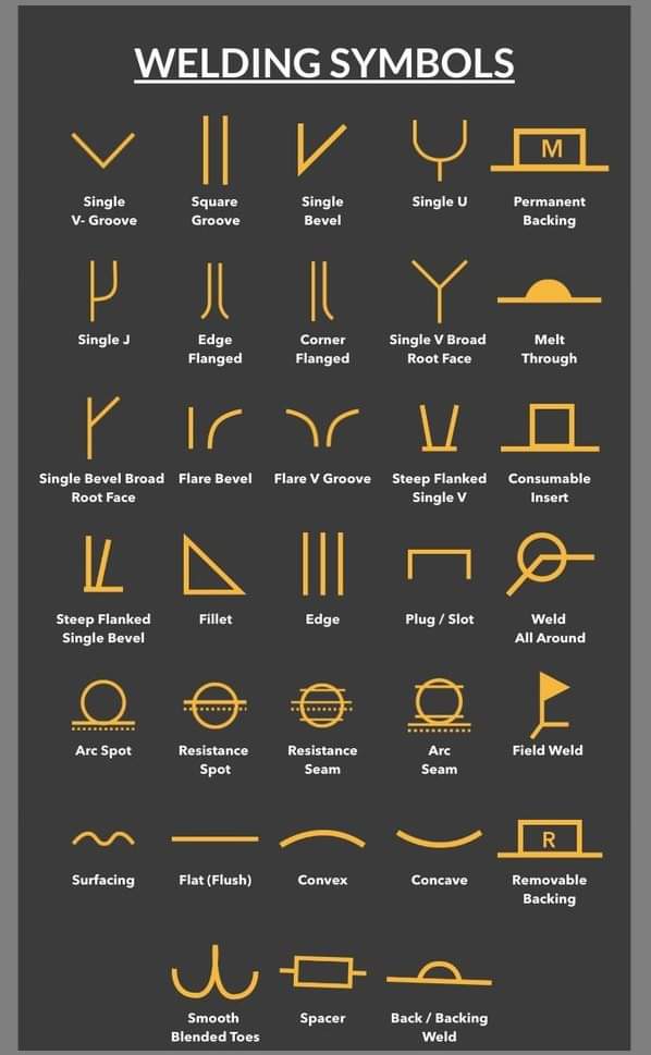
Figure 7.18 shows the most common weld types also called weld symbols, and characterize an important part of the overall welding symbols. A weld symbol is component of welding symbol, indicating type of weld to be used The welding symbol is the entire symbol.

Different Types of Symbols
Several different types of welding symbols can be used, each with their own specific meaning. Some of the most common types include:
Fillet weld symbols
Used to indicate a fillet weld, which is a type of weld that creates a triangular shape at the joint. The size of the weld is indicated by the length of the reference line.
Groove weld symbols
Used to indicate a groove weld, which is a type of weld that is made by welding the two parts of a joint together in a V-shape. The size and type of the groove is indicated by the shape of the symbol.
Spot weld symbols
Used to indicate a spot weld, which is a type of weld that joins two parts of a joint together in a small circular area. The size of the spot weld is indicated by the diameter of the symbol.
Plug or slot weld symbols
Used to indicate a plug or slot weld, which is a type of weld that fills a hole or slot in one of the parts of the joint. The size of the hole or slot is indicated by the dimensions of the symbol.
When applying welding symbols, it is important to:
- Use the correct symbol for the type of weld
- Place the symbol on the correct side of the reference line
- Indicate the size of the weld correctly
- Use the appropriate leader lines to connect the symbol to the point on the technical drawing or blueprint where the corresponding weld will be made
It is also important to ensure that the symbols are placed in a location that is easily visible and can be easily interpreted by the welder.

Placement of Weld Symbols
Following are the ways of placing weld symbol on the reference line.
- If the weld symbol is placed at the top of the reference line, it refers to a weld that is to be made on the other side of the joint relative to the arrow location.
- If it is on the bottom of the reference line, it refers to a weld that will be made on the same side of the joint as the arrow.
- If weld symbols are placed on both sides of the reference line that would indicates a two‐sided weld joint.
Figure 7.19 shows examples of butt joint, T joint, and lap joint. The arrow side placed on the side of the joint that is closest to the arrow. In symbolic representation, the welding symbol’s arrow should be touching the joint at the weld location as shown in example. The arrow may be pointing up or down relative to the reference line, see in these examples the arrows pointing downwards.
Figure 7.20 shows the placement of the weld symbol and welding results produced from these welding symbols. The example shows a V groove. Also note the difference in the weld location depending on which side of the reference line the symbol is placed. i.e., top of the reference line, it refers to a weld on other side and bottom of reference line refers weld on same side. If weld symbols are placed on both sides of the reference line that would indicates a two‐sided weld joint.
Figure 7.21 shows an example of groove weld symbol for joint preparation on one side. For joint preparation on one side of joint a break in the arrow is added to indicate the arrow in side of joint where the groove (bevel or J groove) will be placed. If there is no break in the arrow that means it can be on either side the joint preparation could take place.
Types of Weld Symbols
- For non-symmetrical weld symbols i.e., bevel, fillet, or J groove, the vertical member is always on left side regardless of arrow direction (See Figure 7.22). Some symbols also provide other information like weld process or material being welded. See example in (Figure 7.22) having optional tail, used to provide other information like weld process or material being welded.
- Sometimes supplementary symbols are also added to the arrow line example (shown in Figure 7.23). weld‐ all‐around symbol is an example of supplementary symbols. It refers the welder to produce the weld all the way around the part being welded see (Figure 7.24).
- The field weld symbol indicates that the weld is to be made in the field.
- The melt‐through symbol is used for complete penetration welds that are made from one side only, and calls for visible root reinforcement.
- The contour symbols indicate the final shape of the weld. If there is no letter next to the symbol signifying the finishing process to be used to create the shape (such as “G” for grinding, or “M” for machining), then the contour specified is to be created by the welding process.

Dimensions in Welding Symbols
Welding symbols also provides information about dimensions such as root opening, bevel angle, length and pitch of intermittent welds, and weld sizes. The locations for these dimensions in welding symbols are shown in Figure 7.25. In case of multiple welds or multiple operations on a welding symbol can be indicated using multiple reference lines or multiple symbols stacked on each other (see Figure 7.26). In the case of multiple reference lines, the line that is closest to the arrow is performed first. In the case of multiple stacked symbols, the symbol closest to the reference line is performed first.

Credits [Welding Engineering An Introduction-Wiley (2016)]
Weld Length
The length component is an important factor in each welding. Weld length is not applicable in spot and plug wildings. Sometimes the weld length is considered as some portion of the weld and sometimes length of entire weld is considered. The weld information is presented on drawing though different methods. When the entire length is considered, then it is not necessary to mention the length on welding symbol. Usually the welding symbol is responsible to point out the joint where the welding is to be done. If the welding require to change the direction a multi-arrow symbol or additional welding symbol is used. Welding length is mentioned on right side of the weld symbol, when no changes are required in the length.
Intermittent Weld
An intermittent weld also known as skip weld is a series of weld segments that are done on a joint. Each weld segment in series have two components one is length and other is pitch. The length component is linear distance of each weld segment and whereas pitch is the distance between the centers of two adjacent weld segments. And this is mentioned with a dash between the two welding symbols. And it is placed on the right side of the length on welding symbol.
FAQs
Why do you need to have knowledge about welding symbols?
Welding symbols are used to specify the type of weld, its size and other details on technical drawings and blueprints. They are important to ensure that the welding is done correctly and to the appropriate specifications.
What are the important rules observed while applying weld symbols?
Some important rules to observe when applying weld symbols include using the correct symbol for the type of weld, and placing the symbol on the correct side of the reference line.
How many welding symbols do you need?
The number of welding symbols needed will vary depending on the project and the number of welds required.
Are welding symbols universal?
Welding symbols are not universal, but there are a few different national and international standards that are commonly used, such as the American Welding Society (AWS) and the International Institute of Welding (IIW).
Can a welding symbol have more than one arrow?
A welding symbol can have more than one arrow, for example, if multiple passes are required for the weld.
Where do weld symbols go?
Weld symbols are typically placed near the point on the technical drawing or blueprint where the corresponding weld will be made.
What is the main component of weld symbol?
Do you read a weld symbol left to right?
What is the most common type of weld symbols?
The most common type of weld symbols is the fillet weld symbol. Fillet welds are the most widely used type of weld, and the fillet weld symbol is used to indicate the size and type of fillet weld required. It is also important to note that the other types of weld symbols, such as groove weld symbols, spot weld symbols, plug or slot weld symbols also have their significance in specific welding applications.
Conclusion
In conclusion, welding symbols are a crucial aspect of the welding industry, making it easier for welders to understand the requirements of a project. By understanding the basics of welding symbols, welders can ensure that the welding is done correctly and to the appropriate specifications. This worksheet has covered the different types of symbols and how to properly apply them, and it is a great resource for anyone looking to improve their understanding of welding symbols.