Hydrogen Cracks in Steel: Causes & Prevention
Hydrogen cracks in steel — often called hydrogen-induced cracking (HIC), cold cracking, or delayed cracking — is a stealthy enemy in welding and metal fabrication. It can appear minutes, hours, or even days after welding, seemingly out of nowhere, and cause brittle fractures that compromise safety, performance, and service life. For welders, engineers, and inspectors, understanding the root causes and proven prevention strategies is essential.
Basic Concepts
What is hydrogen in steel?
Hydrogen in steel is not a single thing — it exists in different physical states and interacts with the metal microstructure. Atomic hydrogen (single hydrogen atoms) is extremely mobile in steel and can diffuse through the lattice. Once hydrogen recombines to form H₂ molecules or becomes trapped at defects, its behavior changes. Those trapped hydrogen atoms or molecules cause the problems we call hydrogen cracking.
Forms of hydrogen (atomic, molecular, trapped)
Atomic hydrogen (H): Highly mobile, can travel quickly through the metal lattice.
Molecular hydrogen (H₂): Formed when atoms pair up; less mobile, can generate internal pressure in voids.
Trapped hydrogen: Hydrogen bound to dislocations, precipitates, inclusions, grain boundaries, or pores. Traps can be reversible (hydrogen can leave under thermal activation) or irreversible (deep traps).
Definitions: HIC, SOHIC, delayed cracking, cold cracking
Hydrogen Induced Cracking (HIC): Broad category of cracking due to hydrogen presence.
Stress-Oriented Hydrogen Induced Cracking (SOHIC): Hydrogen-induced cracking that advances perpendicular to applied tensile stress, often beneath surfaces in sulfide stress cracking (SSC) situations.
Delayed (cold) cracking: Cracking that occurs after welding when residual stresses and trapped hydrogen combine; called “cold” because it happens at ambient temperature.
Mechanisms of hydrogen-induced cracking
Hydrogen cracking results from a combination of hydrogen presence, a susceptible microstructure, and tensile stress. Several physical mechanisms have been proposed and observed:
Hydrogen diffusion and trapping
Hydrogen diffuses rapidly through steels. When it reaches traps — dislocations, non-metallic inclusions, or grain boundaries — it can accumulate. Reversible traps can release hydrogen on heating; irreversible traps hold it firmly. The concentration and distribution of trapped hydrogen govern where cracks might initiate.
Reversible vs irreversible traps
Reversible traps (e.g., Cottrell atmospheres around dislocations) release hydrogen with modest heating and are associated with delayed cracking.
Irreversible traps (e.g., carbides, large inclusions) hold hydrogen more permanently and can form pressure pockets or embrittlement sites.
Hydrogen-enhanced decohesion
Hydrogen reduces the cohesive strength between atoms at grain boundaries or interfaces. In regions where hydrogen concentration is high, the metal can separate more easily under stress — imagine tiny lubricants weakening the glue between metal grains.
Hydrogen-enhanced localized plasticity (HELP)
Hydrogen can increase dislocation mobility locally, causing highly localized plastic deformation which then leads to microvoid formation and crack initiation. This mechanism explains how hydrogen can make otherwise ductile material behave in a brittle way.
Pressure build-up in voids and hydrogen-assisted cracking
When hydrogen recombines to form molecular hydrogen in voids or inclusions, the resulting pressure can drive crack propagation. It’s like water vapor in a sealed pocket heating and expanding — internal pressure helps open cracks.
Common sources of hydrogen
Identifying where hydrogen comes from is the first practical step toward prevention.
Moisture and hydrocarbons in shielding gases and flux
Moisture contamination in shielding gas lines, flux-cored wire, or flux can generate hydrogen during welding. Even small amounts of water vapor break down at arc temperatures producing atomic hydrogen.
Surface contamination (oil, grease, salts)
Hydrocarbons and chlorinated or salt contaminants on surfaces liberate hydrogen when heated. Salt residues (chlorides) are especially insidious because they also promote corrosion that can generate hydrogen.
Wet or incorrectly stored electrodes and filler metals
Electrodes or filler metals that absorb moisture will release hydrogen during welding. Stick electrodes, flux-cored wires, and fluxes are particularly sensitive and often require baking to remove moisture.
Corrosion reactions and electrochemical hydrogen charging
Corrosion processes (e.g., acid pickling, cathodic reactions) can produce hydrogen atoms that enter steel. Electrochemical hydrogen charging in service (e.g., cathodic protection misapplication) can also add hydrogen.
Manufacturing processes (pickling, electroplating, soaking)
Pickling, acid cleaning, electroplating, and exposure to hydrogen-containing atmospheres during heat treatment introduce hydrogen into the steel if not followed by proper baking or degassing.
Factors that increase susceptibility
Hydrogen alone rarely causes immediate failure; susceptibility depends on several interacting factors.
Steel chemistry (carbon, Mn, P, S, alloying elements)
Higher carbon and certain alloying elements increase hardenability and raise the risk of forming brittle microstructures like martensite. Elements like phosphorus and sulfur can segregate to grain boundaries and compound hydrogen’s embrittling effects.
Microstructure (pearlite, martensite, bainite, ferrite)
Martensite and high-bainite microstructures are most susceptible because they are harder and less ductile.
Ferrite-rich, low-strength microstructures are generally less susceptible.
Control of cooling rate and alloy content therefore directly influences hydrogen cracking risk.
Hardness and strength levels
There’s a practical relationship: as hardness (or tensile strength) increases, resistance to hydrogen cracking decreases. Many codes use hardness limits as criteria for acceptance.
Residual and applied stresses
Tensile residual stresses from welding shrinkage or external loads are a key driver for delayed cracking. Without tensile stress, hydrogen is less likely to open cracks.
Temperature and service environment
Lower temperatures slow hydrogen diffusion but also make materials less ductile. Ambient or moderately elevated temperatures can release trapped hydrogen (if preheat/postheat applied), reducing risk.
Weld geometry and restraint
High restraint and sharp geometry changes focus stresses and provide initiation sites. Single-pass welds with low restraint are less problematic than heavily restrained multi-pass welds on thick plates.
Detection and inspection methods
Finding hydrogen cracks sometimes requires more than visual checks.
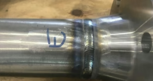
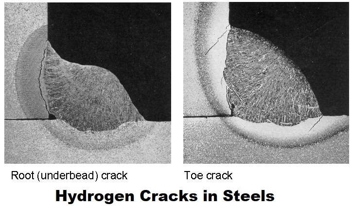
Visual inspection and localized cracking signs
Surface indications include fine, often branching cracks near weld toes, HAZs, or heat-affected interior zones. Delayed cracking may appear as brittle fracture surfaces later on.
Non-destructive testing (UT, MT, PT, radiography)
Magnetic Particle Testing (MT): Good for surface and near-surface cracks in ferromagnetic steels.
Penetrant Testing (PT): Effective for open-to-surface cracks.
Ultrasonic Testing (UT): Detects internal cracking and can characterize depth.
Radiography: Shows volumetric defects but can miss tight cracks aligned with the beam.
Choose the NDT method based on expected crack orientation and location.
Metallography and hydrogen analysis (TDS, SIMS)
Metallography reveals microstructural evidence of cracking mechanisms. Thermal Desorption Spectroscopy (TDS) quantifies trapped hydrogen; secondary ion mass spectrometry (SIMS) maps hydrogen at microscopic scales in research contexts.
Mechanical testing for susceptibility (HJ test, SSRT, bend tests)
Specialized tests assess susceptibility under controlled hydrogen charging or stress conditions. These are typically used in R&D, material qualification, or failure investigations.
Prevention and mitigation strategies
Preventing hydrogen cracking requires attacking all three legs of the “hydrogen — susceptible microstructure — tensile stress” tripod.
Material selection and control
Choose steels with lower hardenability and appropriate chemistry for the service. Microalloying and controlled processing can reduce susceptibility without sacrificing strength. When possible, select grades with documented low hydrogen cracking susceptibility.
Low-hydrogen steels and microalloying
Steels engineered for lower hydrogen uptake and cleaner inclusion populations are far less likely to HIC. Microalloying (e.g., Nb, Ti) can refine grain structure and reduce sensitivity.
Design and fabrication practices
Design to minimize restraint — use joints that allow deformation, add filler to reduce stress concentration, and avoid abrupt geometry changes. Proper fixturing that allows movement during welding reduces residual tensile stress.
Minimize restraint, reduce sharp transitions
Fillets and smooth transitions spread stresses. Avoid over-tight clamping where possible; use tack welds that permit movement but still control alignment.
Preheat and interpass temperature control
Preheating slows cooling rates, reducing hard microstructures and allowing hydrogen to diffuse out during welding. Interpass temperature control prevents the formation of brittle microstructures in multi-pass welds.
Post-weld heat treatment and stress relief
Post-weld heat treatments (PWHT) can lower residual stresses and allow hydrogen to escape by elevating temperature long enough for desorption. Stress-relief cycles should be tailored to steel composition and thickness.
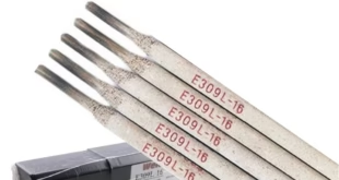
Use of low-hydrogen consumables and electrode baking
Low-hydrogen electrodes and filler metals produce less hydrogen at the arc. Stick electrodes and flux-cored wires should be stored dry and baked according to manufacturer recommendations before use.
Proper cleaning and degreasing
Remove oils, greases, salts, and moisture before welding. Simple solvent cleaning plus baking or drying can sharply reduce hydrogen sources.
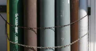
Control of environment (dry gas, humidity control)
Keep the workspace dry. Use dry shielding gas lines, purge chambers, and humidity controls in storage and welding areas if practical.
Cathodic protection and coatings (where applicable)
Be cautious: while cathodic protection prevents corrosion, incorrect application can generate atomic hydrogen and increase HIC risk, especially in high-strength steels. Coatings that seal the surface from moisture and salts can help but must be compatible with the welded joint.
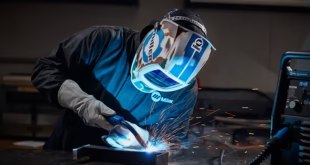
Practical welding guidelines to avoid hydrogen cracking
Step-by-step checklist for welders
Clean joint surfaces: remove oil, grease, salt, and mill scale.
Store electrodes/wire in dry containers; bake if required.
Preheat to the recommended temperature based on steel grade and thickness.
Use low-hydrogen consumables and correct welding parameters.
Control interpass temperatures.
Minimize restraint and avoid welding long, continuous runs without pauses.
Consider PWHT or stress relief where appropriate.
Inspect with PT or MT before placing in critical service.
Typical preheat/postheat temperature charts (by hardness/steel grade)
As a rule of thumb: higher hardness and higher carbon equivalency require higher preheat. Many welding codes provide specific charts — if hardness or CE (carbon equivalent) is high, preheat is often mandatory. When in doubt, consult your procedure specification (WPS) and applicable standards.
How to handle and store consumables
Keep electrodes in an oven at the specified temperature until use.
Store flux-cored wires in sealed containers; re-bake if humidity exposure occurs.
Mark and date containers; rotate stock to avoid long storage in uncontrolled conditions.
Case studies and practical examples
Common real-world failure scenarios
A welded pressure vessel in a humid coastal plant developed delayed cracking in the HAZ because electrodes had absorbed moisture in storage and preheat was not applied.
A high-strength pipeline experienced HIC after acid pickling and inadequate baking — hydrogen introduced during pickling remained trapped and initiated cracks under welding stresses.
Successful prevention story (illustrative)
A fabrication shop struggled with repeated post-weld cracking on high-strength steel frames. By switching to low-hydrogen electrodes, instituting mandatory electrode baking and preheat, revising joint design to reduce restraint, and applying a controlled PWHT, cracking ceased — demonstrating that combined controls at material, process, and design levels work.
Testing, standards, and acceptance criteria
Typical test methods referenced in industry
Industry documents reference a range of tests (HJ tests, electrochemical hydrogen charging tests, HIC testing for sulfide environments). Acceptance criteria commonly use hardness limits, absence of cracks after NDT, or specified mechanical properties post-treatment.
When to reject and when to repair
Reject welded joints if NDT shows cracking beyond allowable size or distribution, or if hardness exceeds specified limits. Repair often requires grinding out the crack area, re-cleaning, re-baking consumables, and using preheat + low-hydrogen procedures to re-weld. For critical components, destructive testing or metallographic verification may be necessary.
FAQs
How soon after welding can hydrogen cracks appear?
Hydrogen cracks can appear minutes to days after welding; delayed cracking commonly shows up within the first 48–72 hours but can manifest later in some conditions. The timing depends on hydrogen diffusion, trapping, and the stress state.
Are all steels equally susceptible to hydrogen cracking?
No. Higher-strength, higher-hardness steels and those with hard microstructures (martensite, high bainite) are more susceptible. Low-carbon, ductile microstructures (ferrite/pearlite) typically resist hydrogen cracking better.
Can hydrogen be completely eliminated from welding?
Not entirely — some hydrogen generation is inevitable during processes involving moisture or hydrocarbons. However, by using low-hydrogen consumables, drying and baking electrodes, controlling environment and preheat/postheat, and reducing contaminants, hydrogen levels can be reduced to safe limits.
Does increasing preheat always prevent hydrogen cracking?
Preheat helps by slowing cooling, reducing hard microstructure formation, and enabling hydrogen to diffuse out. However, preheat alone is not a guarantee — it must be combined with clean surfaces, low-hydrogen consumables, and stress control. Excessive preheat can also cause metallurgical issues in some steels.
How can I tell if a crack is hydrogen-induced or from another cause?
Hydrogen-induced cracks often have characteristic locations (HAZ, weld toes), may be fine and branching, and can appear after a delay. Metallographic examination can show brittle fracture features and trapped hydrogen indicators. Combined failure analysis, including hydrogen measurements and microstructure assessment, is usually required for definitive identification.
Conclusion
Hydrogen cracking is a multifaceted problem that sits at the intersection of metallurgy, chemistry, welding practice, and design. Its prevention is straightforward in principle: remove hydrogen sources, avoid susceptible microstructures, and limit tensile stresses. In practice this requires discipline — good cleaning, proper handling and storage of consumables, correct preheat/postheat, careful material selection, and thoughtful joint design. When these measures are implemented together, the risk of hydrogen-induced cracking drops dramatically. Think of it like a three-legged stool — if you remove any one of the legs (hydrogen, susceptibility, stress), the stool falls over and cracking is unlikely. Good welding procedure specifications (WPS), training, and inspection protocols translate that principle into safe, reliable structures.