Piping Fabrication Tolerances: Standards, Practices, and Control
In any industrial piping system—whether in oil refineries, chemical plants, or power stations—the term “tolerance” holds critical importance. It’s not just about precision; it’s about ensuring that every pipe, flange, and fitting lines up perfectly to form a leak-proof, structurally sound system.
What Are Piping Fabrication Tolerances?
Piping fabrication tolerances refer to the permissible variations in the dimensions and geometry of fabricated piping components. These variations account for inevitable deviations during cutting, welding, machining, and assembly. Without established tolerance limits, even minor inaccuracies could cause misalignment, excessive stress, or complete failure during installation.
Why Tolerances Matter in Piping Systems
Imagine a piping spool off by just a few millimeters in length or flange rotation—it could prevent it from fitting into place on-site, leading to costly rework, delays, and safety issues. Tolerances ensure compatibility, structural integrity, and code compliance. They are the glue that binds the precision of engineering with the reality of hands-on fabrication.
Key Factors Influencing Tolerances in Pipe Fabrication
Design Specifications and Codes (ASME, ANSI, API, etc.)
Each project begins with design blueprints guided by specific codes—such as ASME B31.3 for process piping or API 650 for storage tanks. These codes define allowable deviations for different elements, including angular misalignments, offset distances, and flange alignments.
Material Properties and Manufacturing Variability
Different materials expand and contract and exhibit varying behaviors during fabrication. Stainless steel, carbon steel, and exotic alloys each react uniquely to heat input and stress. Some are more prone to distortion during welding or machining, which must be accounted for in tolerance planning.
Fabrication Methods (Manual vs. CNC)
Manual welding or cutting introduces more room for human error than CNC or automated machines. The more manual the fabrication process, the more liberal the tolerance margins must be. Conversely, digital machines can maintain tighter control, allowing narrower tolerances.
Thermal Effects and Weld Distortion
Welding introduces heat, which causes expansion and subsequent contraction as it cools. If not managed correctly, this can lead to angular distortions or dimensional shifts. Tolerance allowances help accommodate such warping.
Dimensional Tolerances in Piping Fabrication
Linear Tolerances (Length, Offset, and Squareness)
Length tolerances typically range from ±1 mm to ±5 mm depending on pipe diameter and system criticality. Offsets in straight runs or branch intersections are allowed within specific millimeter ranges to ensure system fit-up.
Angular Tolerances (Flange Rotations, Pipe Bends)
Rotational alignment is crucial—especially for flanged connections. For instance, ASME allows flange bolt hole rotation within ±1.5° for general systems. Angular deviations in elbows or offsets must remain within specified degrees or radians.
Ovality and Wall Thickness Variations
Ovality—deviation from perfect roundness—is particularly critical for pipes designed for high pressure. Tolerances are usually expressed as a percentage of nominal outside diameter, e.g., 3% OD. Likewise, wall thickness variation impacts flow and strength, and standards limit how thin or thick it can go.
Fit-Up and Weld Tolerances
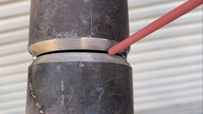
Root Gap and Misalignment Tolerances
When welding two pipe ends, the root gap (space between ends) must fall within a set tolerance—typically 1 to 3 mm—depending on welding procedure. Misalignment of internal walls can also lead to turbulence and failure; hence tolerances are defined (e.g., ≤1.5 mm or 10% of wall thickness).
Weld Joint Preparation and Bevel Angle
The angle and uniformity of weld bevels are standardized (e.g., 37.5° ± 2.5°). Deviations affect weld penetration and fusion quality. Tolerances ensure that welders aren’t compensating too much on-site, preserving weld integrity.
Tolerances for Weld Reinforcement and Undercut
ASME codes specify maximum allowable weld reinforcement (e.g., ≤3 mm for butt welds) and limits for undercut (e.g., ≤0.8 mm deep and not continuous). Exceeding these could lead to fatigue cracks or erosion in service.
Flange and Nozzle Alignment Tolerances
Flange Face and Bolt Hole Alignment
Misalignment here can prevent bolting or cause gasket failure. Flange face flatness is usually limited to ≤0.5 mm over the face diameter, while bolt hole offsets are held within ±2 mm, depending on the bolt size and flange diameter.
Nozzle Projection and Orientation Tolerances
Nozzles on vessels or tanks must project accurately for piping to connect. Tolerances are commonly set at ±3 mm in length and ±1° for angular deviation, ensuring pipes connect without forcing.
Acceptable Tolerances as Codes and Standards
ASME B31.3 Guidelines
ASME B31.3 offers comprehensive tables for tolerances on dimensions, weld fit-up, misalignment, and flange orientation. It accounts for both standard and high-pressure service conditions.
API 650 and Oil & Gas Industry Tolerances
API 650 sets tighter tolerance limits for critical applications like oil tanks. It governs nozzle spacing, verticality, and angularity of shell courses to ensure long-term structural stability.
ISO and DIN International Standards
European and international projects may follow ISO 2768 or DIN 16901 for general tolerances. These offer classes (fine, medium, coarse) to suit fabrication quality levels.
Tolerancing in Pre-Fabricated Spools and Skids
Tolerances in Modular Piping Assembly
In shop-fabricated spools, tolerances must allow for field fit-up. Modular skids, especially in offshore and pharmaceutical units, require tight tolerances to fit into pre-defined plant spaces without field rework.
Site Installation Challenges due to Fabrication Tolerances
Improper tolerances lead to misfits on-site. Field modifications like cold pulls or hot works increase risk and cost. That’s why pipe spools are often “dry fitted” and surveyed before dispatch.
Inspection, Verification, and Quality Control
Tolerance Checks during Fabrication and Assembly
QC teams check tolerances at multiple stages—cutting, fit-up, tack weld, full weld, and final assembly. Non-conformance reports (NCRs) are raised for deviations beyond acceptable limits.
Tools and Instruments Used for Measurement
Tapes, vernier calipers, laser alignment tools, flange alignment pins, digital inclinometers, and total stations are common instruments used in tolerance verification.
Role of QA/QC Inspectors in Tolerance Compliance
Inspectors ensure that all tolerances comply with project specifications and code requirements. Their documentation (e.g., inspection test plans or ITPs) becomes part of the quality record.
Managing and Minimizing Tolerance-Related Errors
Training and Skill Level of Fabricators
Skilled fabricators inherently work within tolerance. Regular training and certification ensure awareness of permissible deviation and practical techniques to stay within range.
Using Templates, Jigs, and Fixtures
Templates standardize dimensions, while jigs and fixtures ensure consistent angular orientation and fit-up during welding or assembly.
Digital Fabrication and Automation to Improve Accuracy
3D scanning, digital layout tools, and automated cutting/welding systems drastically reduce human error and enable tighter tolerances across all components.
Common Challenges and Practical Tips
Dealing with Accumulative Tolerance Stack-Up
Even when each part is within tolerance, stacking multiple components can result in major misalignment. This is called “tolerance stack-up” and must be planned through advanced layout and sequencing.
Best Practices for Tight-Tolerance Fabrication
Always verify against approved drawings, use calibration-checked tools, follow approved WPSs (Welding Procedure Specifications), and apply hold points at critical tolerance stages.
FAQs
What is the typical length tolerance for pre-fabricated piping spools?
Length tolerances typically range from ±1 mm to ±5 mm depending on the pipe diameter and project specifications.
How do fabricators control angular tolerances in flange alignment?
They use flange alignment pins, templates, or digital inclinometers to maintain flange rotation within code-defined degrees.
Are ASME tolerances different from ISO or DIN tolerances?
Yes, ASME, ISO, and DIN all have distinct tolerance classes and measurement criteria. ASME is commonly used in North America, while ISO/DIN are used internationally.
What happens if a fabricated pipe spool is out of tolerance?
The component may require rework, repair, or rejection. Field adjustments can be costly and introduce safety risks.
How can tolerance stack-up be avoided in modular piping fabrication?
Through careful planning, dry fitting, use of jigs, and combining accurate fabrication methods with skilled inspection practices.
Conclusion
Piping fabrication tolerances aren’t just numbers in a codebook—they’re the foundation of structural integrity, safety, and efficiency in every piping system. From the drawing board to final installation, controlling tolerances ensures that each piece of pipe fits precisely into a much larger puzzle. By understanding and applying these tolerance principles correctly, fabricators and inspectors not only meet compliance but also safeguard the entire operation against costly errors and failures.
 Welding of Welders All about Welding and Welders
