Wind Tower Welding and Fabrication Process
Role of Wind Towers in Renewable Energy
Wind towers are the backbone of wind turbines, enabling the conversion of wind energy into clean electrical power. These tall, cylindrical structures elevate the turbine blades to heights where wind speeds are higher and more consistent, ensuring maximum energy output. As global demand for sustainable energy increases, so does the need for advanced and efficient fabrication techniques in wind tower manufacturing.
Basic Structure and Components of a Wind Tower
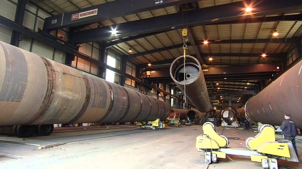
A standard wind tower consists of three main sections: the base, the mid-section, and the top section, often referred to as “cans.” Each section is formed from large rolled steel plates welded together to create a hollow cylinder. Internally, platforms, ladders, cable trays, and support frames are also welded and installed during fabrication.
Materials Used in Wind Tower Fabrication
Selection of Steel Grades
The materials used in wind tower construction must withstand dynamic loading, fatigue, and environmental exposure. Typically, low-alloy high-strength steels such as S355J2 or ASTM A572 Grade 50 are selected due to their balance of strength, ductility, and weldability. Material certification and mechanical testing are prerequisites before use.
Importance of Plate Thickness and Formability
Steel plates used in towers range from 12 mm to 80 mm in thickness, depending on the tower’s height and design loads. The thicker the plate, the more difficult it is to form and weld, demanding precise rolling and preheat parameters to avoid cracking and deformation.
Surface Preparation Standards
Before welding, all plates undergo shot blasting to remove scale and impurities, followed by application of anti-corrosive primer. Surface cleanliness is essential for achieving sound welds and good paint adhesion in later stages.
Overview of the Wind Tower Fabrication Process
Rolling of Steel Plates into Tower Shells
Flat plates are fed into large plate rolls to form cylindrical shells. The quality of this step is critical as incorrect curvature can affect fit-up and cause dimensional issues during assembly. Skilled operators adjust the roll pressure and angles to meet precise diameters.
Fit-up and Tack Welding
Once rolled, the edges of the shells are aligned and tack welded to hold them in place. Accurate fit-up minimizes the risk of internal stresses and weld defects. Automated fit-up systems are often used to ensure uniform alignment.
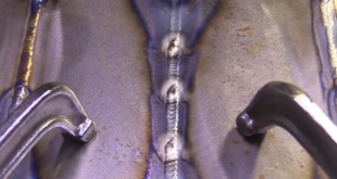
Circumferential and Longitudinal Seam Welding
Shells are joined using longitudinal welds first, then assembled into tower sections using circumferential welds. These welds are mostly done by Submerged Arc Welding (SAW) due to its deep penetration and high deposition rate.
Internal Component Installation (Ladders, Platforms)
Before sealing the tower sections, internal components such as access ladders, working platforms, and electrical cable routes are welded into place. Fixtures ensure proper alignment to meet ergonomic and safety standards.
Welding Techniques in Wind Tower Fabrication
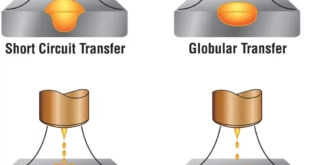
Submerged Arc Welding (SAW)
SAW is the dominant method used for heavy section welding in towers. It offers high productivity, low spatter, and excellent weld quality. Tandem SAW heads are often used to increase deposition rates on thicker plates.
Flux-Cored Arc Welding (FCAW)
FCAW is employed in areas where maneuverability is required, such as fillet welds in internal structures or repair work. It provides good arc stability and faster welding speeds compared to stick welding.
Automatic vs Manual Welding Applications
While most seam welds are performed automatically, some components like flanges and stiffeners may still require manual intervention. Skilled welders must interpret weld symbols, adjust heat input, and monitor bead profiles.
Joint Design and Weld Preparation
Groove Geometry and Backing Strip Usage
Weld joints are designed based on plate thickness, access, and weld process. U-grooves or V-grooves are common in thick sections. Ceramic or steel backing strips are sometimes used to support full penetration welds.
Edge Beveling and Pre-Weld Treatments
Before welding, plate edges are beveled using flame or plasma cutting. These bevels are then ground clean and checked for contamination. Preheat is applied to reduce the risk of hydrogen-induced cracking, especially in thicker plates.
Quality Control in Wind Tower Welding
Pre-Weld Inspection and Joint Alignment
Every weld joint is visually inspected before welding to ensure cleanliness, proper gap, and alignment. Welding Procedure Specifications (WPS) and Welder Qualification Records (WQR) must be strictly followed.
Non-Destructive Testing (NDT) Methods
Ultrasonic Testing (UT)
Used to detect internal flaws like lack of fusion or cracks in thick welds. High-frequency sound waves penetrate the weld, and reflections reveal anomalies.
Radiographic Testing (RT)
X-rays or gamma rays produce images of internal defects. RT is essential for critical joints with high stress exposure.
Magnetic Particle Testing (MT)
Effective for detecting surface or near-surface cracks in fillet and groove welds. It’s often used on flange connections and access welds.
Post-Weld Heat Treatment and Residual Stress Management
Some welds require heat treatment to relieve stresses and improve toughness. This process is done in large furnaces or via localized induction heating, depending on component size.
Challenges in Wind Tower Welding
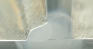
Weld Distortion and Shrinkage
Due to high heat input and long welds, distortion is a common issue. Proper sequence welding, use of jigs, and back-step techniques are employed to minimize this.
Environmental Effects on Welding (Wind, Temperature)
Wind and low temperatures can lead to rapid cooling and hydrogen embrittlement. Shielding enclosures or preheating systems are used when fabricating outdoors.
Weld Access and Vertical Welding
Accessing internal welds and performing vertical-up or overhead welds pose ergonomic and technical difficulties. Automation reduces the need for manual out-of-position welding.
Automation in Wind Tower Fabrication
Column and Boom Manipulators
These are used to automate circumferential and longitudinal welds, ensuring precision and consistency across all shells.
Rotators and Fit-up Systems
Section rotators allow smooth rotation of cylindrical parts during welding, enabling continuous welds with minimum start-stops.
Robotic Welding and CNC-Integrated Systems
For repetitive tasks such as internal component welding or flange attachment, robotic arms guided by CNC systems are employed to increase speed and quality.
Surface Treatment and Corrosion Protection
Blasting and Cleaning Procedures
After welding, the surface is shot-blasted to remove slag, oxides, and contaminants. This ensures coating adhesion and surface integrity.
Coating Systems for Harsh Environments
Epoxy primers, polyurethane topcoats, and zinc-rich paints are applied to protect against saltwater, humidity, and UV. Offshore towers may require multilayered systems with cathodic protection.
Inspection of Coated Surfaces
Coating thickness is measured using dry film thickness gauges. Pinholes and holidays are detected using high-voltage holiday testers to ensure complete coverage.
Final Assembly and Tower Erection
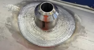
Flange Welding and Bolt-Hole Alignment
Section flanges are aligned and welded with precise bolt-hole orientation to ensure seamless connection during site erection. Tolerances are extremely tight here.
Transportation of Tower Sections
Sections are transported via special trailers or ships and require temporary supports to prevent damage. Lifting lugs are welded and tested beforehand.
Site Welding vs Shop Welding
While most welds are completed in fabrication shops, final connections or repairs may be made onsite. Site welding demands careful control over environment and alignment.
FAQs
What welding process is most used in wind tower manufacturing?
Submerged Arc Welding (SAW) is the most commonly used due to its high deposition rate and deep penetration on thick steel sections.
How thick are the steel plates used in wind towers?
Steel plates typically range from 12 mm to 80 mm, depending on design and location within the tower.
What are the common defects in wind tower welding?
Common defects include lack of fusion, porosity, undercut, and weld misalignment, usually detected through NDT.
Is wind tower welding fully automated?
Not entirely. Seam welds are mostly automated, but internal fixtures and complex areas still require manual welding.
What standards apply to wind tower fabrication?
Standards such as AWS D1.1, EN ISO 3834, IEC 61400, and ISO 9001 guide wind tower fabrication quality and safety.
Conclusion
Wind tower welding and fabrication is a complex, multi-stage process demanding high precision, quality control, and advanced automation. From material selection to final erection, each stage is meticulously planned to ensure the structure’s long-term durability, safety, and performance under harsh operational conditions. With the global shift toward renewable energy, innovations in wind tower fabrication are driving efficiency and sustainability in this vital sector.