How Much Porosity Is Acceptable in a Weld?
Porosity is like the tiny potholes of the welding world — small, hidden, and sometimes harmless, but in the wrong spot or quantity, they can cause catastrophic failure. So, how much porosity is too much? The answer isn’t a one-size-fits-all — it depends on welding codes, application, and criticality.
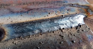
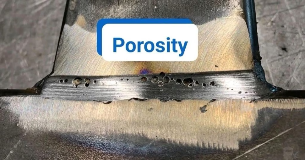
Porosity refers to cavities or tiny holes formed by trapped gas during the solidification of the weld metal. Depending on their size and location, these can be visible or hidden inside the weld.
Think of it like baking bread — if you trap air in the dough, you get bubbles. In welding, though, these gas bubbles weaken the weld rather than fluff it up.
Common Types of Porosity
Surface Porosity
Visible on the weld bead’s surface, this is usually caught during visual inspection (VT). It’s easy to spot but may not always indicate deeper issues.
Subsurface Porosity
Hidden beneath the surface, these are usually detected using radiographic or ultrasonic testing. Subsurface porosity can be more critical as it’s hard to detect and assess.
Wormholes and Cratering Porosity
Wormholes are long, tube-like voids formed by trapped gas following a path during solidification. Cratering porosity happens when the arc is broken too quickly, leaving a pocket at the weld crater.
What Causes Porosity in Welds?
Porosity doesn’t just “happen” — it’s the result of:
Contaminants (oil, rust, moisture)
Incorrect shielding gas or wind interference
Poor electrode or filler storage
Too long an arc length or improper technique
Why Porosity Matters in Weld Quality
Effects on Structural Integrity
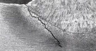
Porosity can reduce tensile strength, create crack initiation points, and impact fatigue life. It compromises the mechanical properties of the weld, especially if located in high-stress regions.
Visual vs. Volumetric Inspection Issues
Not all porosity is visible. Surface porosity may be only the tip of the iceberg, especially in critical pressure vessels or pipelines. That’s why codes often call for RT or UT, not just VT.
Welding Codes and Acceptance Criteria
Overview of Common Standards
AWS D1.1 (Structural Welding Code – Steel)
Widely used for structural steel in buildings and bridges. It provides detailed acceptance criteria based on discontinuity type, length, and spacing.
ASME Section IX
Primarily used in pressure piping and boilers. Acceptance is tied to service pressure, material, and welding process.
ISO 5817 and EN 1090
Used internationally. ISO 5817 classifies weld quality into Levels B (stringent), C (intermediate), and D (basic) — each with their own porosity limits.
Factors Affecting Porosity Acceptance
Welding Process Used
TIG and MIG welds are held to higher visual standards than SMAW due to their cleaner appearance. Processes like FCAW (especially self-shielded) are more prone to porosity.
Material Type and Thickness
Thinner materials or exotic alloys (like aluminum) often have tighter tolerances due to their service expectations and susceptibility to defects.
Service Conditions of the Weld
Critical load-bearing or high-pressure applications have less tolerance for porosity compared to cosmetic or low-stress applications.
Acceptable Limits of Porosity According to Major Codes
AWS D1.1 Porosity Acceptance Criteria
Individual surface pores: ≤3/32” (2.4 mm)
Clustered porosity: max 3/8” (9.5 mm) in 12” of weld
Spacing: Must be separated by at least 1” (25 mm) to be acceptable
ASME B31.3 and Section VIII Rules
Volumetric porosity may be acceptable if scattered and small
Cluster porosity or aligned porosity usually disqualifies the weld
Acceptance is often per RT interpretation
ISO 5817 Classifications (B, C, D Levels)
Level B (Stringent): Minimal porosity, for aerospace and nuclear
Level C (Normal): Some porosity allowed, typical for general fabrication
Level D (Basic): Looser limits, suitable for non-critical welds
Field vs. Shop Welding: Practical Tolerance Differences
Real-World Inspection Approaches
In the field, inspectors often weigh the context — if a weld meets code and functionally performs under pressure, minor porosity might be tolerated.
Tolerances in Critical vs. Non-Critical Welds
Bridges, pressure vessels, and load-bearing components get zero tolerance for clustered porosity. On railings, gates, or cosmetic parts? Slight porosity is often acceptable.
Porosity Detection Methods
Visual Testing (VT)
Quick, cheap, and effective — but only useful for surface defects.
Radiographic Testing (RT)
Ideal for detecting subsurface porosity. Shows size, location, and distribution but is costly and requires skilled interpretation.
Ultrasonic Testing (UT)
Not as effective for gas pockets, but useful for slag inclusions and cracks. Often used in thicker materials where RT is impractical.
Repair or Reject? Decision Making Based on Porosity
Evaluating Size, Location, and Distribution
A single large pore in the weld root could mean automatic rejection. But ten tiny, scattered pores on the toe of a fillet weld? Maybe acceptable.
Cost-Benefit Analysis of Rework
If porosity is near the surface and easy to fix, it’s often repaired. But excessive grinding or repair welding can do more harm than good — sometimes, acceptance is safer than correction.
Reducing and Preventing Weld Porosity
Electrode and Wire Considerations
Use low-hydrogen electrodes (e.g., E7018)
Keep filler wire dry and sealed
Shielding Gas and Environment
Use proper gas flow (20–30 CFH for MIG/TIG)
Block wind during outdoor welding
Cleaning and Fit-Up Practices
Grind off rust, oil, paint
Ensure tight fit-up with no gaps for gas to get trapped
Case Studies: Porosity in Critical Applications
Pipeline Welding
API 1104 allows some scattered porosity, but anything in root pass is usually rejected. Critical service demands zero tolerance in many zones.
Aerospace Welding
Almost all porosity is unacceptable — even microscopic defects are rejection-worthy due to extreme stress and pressure.
Structural Steel Projects
Porosity is evaluated based on location and code — AWS D1.1 gives practical thresholds, but inspectors are trained to err on the side of caution.
FAQs
Can you weld over porosity to fix it?
Yes, but only if the defect is shallow and cleaned properly before re-welding. Otherwise, it may trap more gas and worsen the problem.
Is any porosity acceptable in pressure piping?
Only scattered and very small porosity is acceptable. Cluster or aligned porosity typically results in rejection under ASME and API standards.
How can I check for internal porosity without X-ray?
Ultrasonic testing can help, but it’s limited. RT remains the gold standard for internal gas pocket detection.
What is the most common cause of porosity in MIG welding?
Poor shielding gas coverage, often due to wind, incorrect flow rate, or nozzle contamination.
Does porosity always weaken a weld?
Not always — small, scattered pores may have little effect in low-stress applications. But in critical welds, even minor porosity can reduce strength and durability.
Conclusion
Porosity is one of the most misunderstood weld defects. It’s not always a deal-breaker, but it must be evaluated in context, against codes, service conditions, and criticality. While perfect welds are rare, safe welds are always the goal. Know the standards, inspect smartly, and decide wisely — that’s how you balance code compliance with real-world conditions.