Understanding Acceptable Welding Undercut and Its Acceptance Criteria
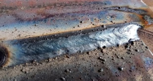
Welding undercut is a groove melted into the base metal adjacent to the weld toe that isn’t filled with weld metal. While some degree of undercut may seem minor, excessive or poorly formed undercut can reduce fatigue life, create stress risers, and ultimately compromise structural integrity. In tanks, pipelines, and pressure vessels, such flaws can lead to premature failure. That’s why industry standards — especially API 650 for storage tanks — enforce strict Acceptance Criteria for Undercut.
The Purpose of Undercut Acceptance Criteria
Why Are These Limits Necessary?
Undercut is a concern because it can:
Act as a stress concentrator.
Weaken fatigue resistance.
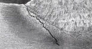
Create starting points for cracks.
Acceptance criteria are set to balance practical weld production with engineering reliability. Depending on the application—whether static or dynamic, structural or pressurized—standards may be strict or slightly forgiving.
The 10% Rule of Thumb for Undercut Depth
One commonly used guideline in both education and industry is:
Undercut depth should not exceed 10% of the base metal thickness or 0.5 mm (0.02 inches), whichever is less.
This rule is particularly useful when:
No formal code applies.
Visual inspection is being used.
Welder qualification tests are performed.
For example:
On an 8 mm thick plate: 10% = 0.8 mm → limit becomes 0.5 mm.
On a 3 mm plate: 10% = 0.3 mm → limit becomes 0.3 mm.
It provides a conservative and easy-to-apply threshold to prevent undercut from reducing the effective cross-section of the base material.
AWS D1.1 Structural Welding Code Criteria
General Acceptance Limits
In AWS D1.1, the criteria for acceptable undercut depend on service loading:
For static loading:
Undercut is acceptable if no deeper than 1/32” (0.8 mm).
For cyclic loading (fatigue-sensitive members):
Undercut must not reduce the base metal thickness by more than 1/32” (0.8 mm).
Must be smooth and well-blended if present.
Key Notes for AWS Visual Inspection
AWS encourages use of undercut gauges and clear visual indicators.
AWS also refers to cumulative criteria when multiple defects are present in the same weld segment.
ASME Boiler and Pressure Vessel Code (BPVC)
The ASME BPVC, particularly Section VIII and Section IX, applies to pressure vessel welding and qualifications.
ASME Undercut Criteria
Typically allows maximum 1/32” (0.8 mm) for manual or semi-automatic welds.
GTAW welds or thin materials may have stricter requirements, defined by WPS or engineering judgment.
Welds on pressure parts must avoid sharp discontinuities that can act as crack initiation sites.
These criteria are widely used in oil & gas, nuclear, and pharmaceutical applications where pressure integrity is paramount.
ISO 5817: International Weld Quality Standard
ISO 5817 defines Quality Levels B, C, and D with varying levels of stringency:
| Quality Level | Max Allowable Undercut |
|---|---|
| B (stringent) | 0.2 mm |
| C (moderate) | 0.5 mm |
| D (lenient) | 1.0 mm |
Smooth blending of the undercut.
No sharp grooves or unfilled notches.
Consideration of total undercut length for long weld runs.
API 650: Criteria for Welded Storage Tanks
API 650 is widely used for designing atmospheric storage tanks in the oil and chemical industry. It outlines specific undercut acceptance limits in Section 9 (Welding Requirements) and Annex U (Visual Inspection Acceptance Criteria).
Key Acceptance Criteria from API 650:
Undercut depth shall not exceed 1/32″ (0.8 mm) for all primary welds unless otherwise specified.
For shell-to-bottom welds, which are critical zones, the undercut should be completely absent or ground smooth.
API 650 strongly emphasizes visual acceptance—if the undercut shows signs of irregularity or excessive penetration, repair is mandatory.
Additionally, API 650 often references AWS D1.1 and ASME IX for supplementary guidance during inspection and repair.
Length-Based Limitations: Total Undercut Length
In addition to depth, the total length of undercut in a given weld segment is sometimes limited.
A general best practice (especially when not explicitly stated by a code) is:
Total undercut length in any 300 mm (12″) weld segment should not exceed 10% of that length (i.e., 30 mm or 1.2″).
This ensures that undercut—even if shallow—does not accumulate and create stress zones across long welds. ISO 5817 and API 650 do not always list a percentage but emphasize continuous undercut avoidance, especially in shell courses and lap welds.
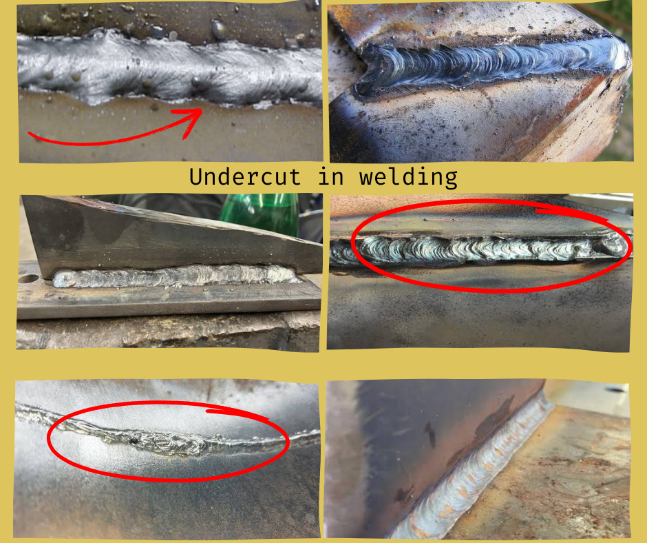
Visual Inspection Techniques for Undercut
Tools Commonly Used
Undercut gauges (stepped feeler type)
Weld profile gauges
Flashlight and mirror
Digital calipers or portable profilometers
Inspector Best Practices
Look at light reflection to spot grooves.
Use go/no-go templates for fast go/no-go assessment.
Ensure no sharp notches or discontinuities at start/stop points.
Visual inspection, especially under codes like AWS and API 650, remains the frontline quality assurance method.
Repair and Prevention of Undercut
Repair Techniques
Grinding/blending the undercut until smooth.
Filling with a capping pass using low amperage and controlled travel speed.
Removing the defective area and rewelding if depth exceeds limit.
Preventive Welding Practices
Maintain correct electrode angle.
Use short arc with correct polarity.
Adjust travel speed and voltage—too fast = more undercut.
Ensure interpass cleaning to avoid slag inclusions near the toe.
Applying Engineering Judgment
While standards provide numbers, experienced weld engineers often apply engineering judgment when dealing with:
Slightly excessive but well-blended undercuts.
Welds in non-critical or non-cyclic areas.
Welds subject to post-weld heat treatment, where stress relief may mitigate undercut concerns.
Codes like ASME and API allow for engineering acceptance, especially when supported by stress analysis or testing.
Conclusion
Undercut in welding, while sometimes minor, can drastically reduce weld performance if left unchecked. Various standards, including AWS D1.1, ASME BPVC, ISO 5817, and API 650, provide clear acceptance criteria—usually limiting undercut to 0.5–0.8 mm.
Across industries, the “10% of base metal thickness” rule and length limitations like “not more than 10% of weld segment” offer practical guidance where code language is vague. These practices ensure welds remain strong, safe, and serviceable—especially in critical infrastructure like storage tanks, structural frames, and pressure vessels.