What Is Hot Cracking (Solidification Cracking)?
Quick Definition and Why It Matters
Hot cracking—also called solidification cracking—is a weld defect that forms while the weld metal is still hot and partly solid, when weak liquid films at grain boundaries cannot accommodate shrinkage and tensile strains, causing the solidifying weld to tear.
Where and when it occurs in welding
It happens during the final stages of solidification—typically along the weld centerline or in the crater at arc termination. In some alloys, a related phenomenon occurs in the heat-affected zone (HAZ) called liquation cracking, where partially melted boundaries fail as the HAZ cools.
Why inspectors and fabricators care
Hot cracks are structurally serious (planar, sharp flaws) and often sub-surface, so they may pass casual visual checks but undermine load-bearing capacity and fatigue life. Because they form immediately as the weld solidifies, you cannot “heal” them by post-heat; you must prevent or remove and repair.
The Metallurgical Mechanism—What Actually Cracks
Solidification range and “mushy” zone
When a weld pool cools, it does not jump from liquid to solid at a single temperature. Most engineering alloys have a solidification range. Between the liquidus and solidus, the pool becomes a mushy zone—a network of growing solid dendrites permeated by inter-dendritic liquid. Mechanical strength is poor in this state.
Grain boundary liquid films and segregation
As dendrites grow, solute elements with low solubility in the solid—such as S, P in steels or Cu, Mg, Zn in aluminum alloys—segregate to the last liquid to solidify. These enriched liquids form low-melting eutectics that wet grain boundaries and interdendritic channels. The result is a skeleton of solid grains glued together by thin, weak liquid films.
Strain during solidification and feeding failure
While the mushy zone exists, the weld is subjected to:
Solidification shrinkage (liquid → solid volume change),
Thermal contraction of hot metal,
External restraint from the joint and base metal.
The roles of bead shape, restraint, and cooling rate
Bead shape: Deep, narrow welds have long, parallel columnar grains meeting at the centerline. This geometry concentrates strain along the centerline and limits liquid feeding—prime conditions for a longitudinal centerline crack.
Restraint: Tight fit-ups, large, rigid assemblies, and short stitch welds on thick sections all raise instantaneous tensile strain as the weld solidifies.
Cooling rate: Very high travel speeds or improper heat input can create a thin mushy zone with poor feeding. Conversely, excessively high heat input can promote coarse grains and segregation—there’s a process window to aim for, not just “more” or “less” heat.
Types of Hot Cracking
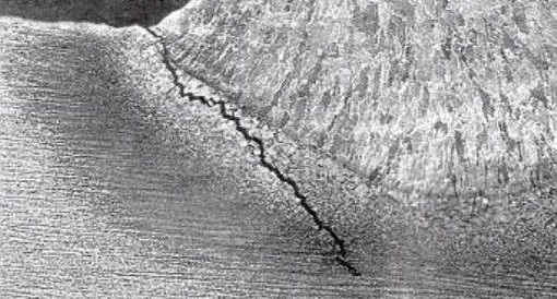
Centerline (longitudinal) solidification cracking in the weld metal
This is the classic form—a crack parallel to the weld axis, often starting at the root and propagating through the last-to-solidify center. It can be continuous or intermittent and may be sub-surface until macroetching reveals it.
Crater cracking at weld terminations
When the arc stops without properly filling the crater, a star-shaped or cross-shaped crack can form as the central pool shrinks with insufficient liquid to feed the center. It is common in GTAW and GMAW when crater fill features aren’t used.
HAZ liquation cracking (distinct but related)
Adjacent to the fusion line, susceptible alloys may see partial melting along grain boundaries. Upon cooling, these thin films cannot carry strain and tear. Though not strictly “solidification” of the weld metal, it occurs at high temperature during cooling and is often grouped with hot cracking for practical prevention.
Microfissuring in high-alloy systems
In some nickel-base and austenitic alloys, very fine microfissures can form within the weld or HAZ due to particular carbide/boride eutectics and impurity levels. Individually tiny, they can link under service conditions.
Materials Susceptibility
Carbon and low-alloy steels—effects of S, P, and Mn/S ratio
Steels are generally forgiving, but sulfur (S) and phosphorus (P) segregate strongly and form low-melting compounds. Adding manganese (Mn) ties up sulfur as MnS, raising the melting point of the last liquid. A high Mn/S ratio (commonly targeted by filler selection and steelmaking) improves resistance. Dirty steels or recycled feeds with elevated S, P, or tramp elements are noticeably worse.
Austenitic stainless steels—delta ferrite effect
Fully austenitic (100% γ) weld metals are prone to hot cracking because austenite dissolves little S and P, and interdendritic liquid cannot be buffered. Maintaining a small fraction of δ-ferrite in the weld metal—commonly a Ferrite Number (FN) in the single digits—dramatically lowers cracking risk because ferrite absorbs impurities and provides crack-blunting pathways. Filler selection (per Schaeffler/DeLong/WRC diagrams) is the usual lever.
Aluminum and its alloys—long freezing range alloys (2xxx, 7xxx, some 6xxx)
Aluminum systems with long solidification ranges and eutectics (e.g., high Cu or Zn+Mg) are notorious for hot cracking. The 2xxx and 7xxx series are at the severe end; some 6xxx alloys show moderate susceptibility depending on Mg/Si balance and filler choice. Proper filler alloy selection to narrow the freezing range and promote equiaxed grains is key.
Nickel-base and other special alloys
Nickel alloys with B, S, Si and certain carbide/boride formers may microfissure if procedure windows are exceeded. Copper alloys, some magnesium and cobalt systems can also hot tear depending on composition and restraint.
Process and Procedure Factors That Increase Risk
High heat input vs. travel speed and bead geometry
Too high heat input → coarse columnar grains and extended segregation.
Too low heat input or too high speed → inadequate fusion and “skinny” beads that starve the centerline of feed metal.
Practical control means staying in a balanced window appropriate to the alloy and joint.
Deep, narrow penetration profiles
Processes or techniques that produce finger-like penetration (e.g., certain spray GMAW, high-current GTAW, laser/EB hybrid effects) can align grains toward the centerline and concentrate shrinkage, increasing centerline cracking.
High restraint joints and poor fit-up
Corner joints on heavy plate, full-penetration welds with tight root faces, and short, intermittent beads in rigid frames introduce high thermal stresses right as the weld solidifies.
Contamination, tramp elements, and recycled feedstock variability
Oil, paint, and shop grime introduce undesired elements; recycled feedstock can raise S, P, or Cu. Cleanliness and vetted consumable sources are underrated defenses.
Hot Cracking Differs from Cold Cracking
Temperature window and timing
Hot cracking: at high temperature, during solidification (or very shortly after) while the weld is still red-hot.
Cold cracking: at low temperature (minutes to hours after welding), generally below ~200 °C, driven by hydrogen, hard microstructures, and restraint.
Metallurgical drivers and prevention levers
Hot cracking levers: composition, bead shape, heat input, restraint, filler choice, crater fill.
Cold cracking levers: preheat, low-hydrogen consumables, bake/outgassing, tempering—measures that do not solve hot cracking directly.
Typical locations and visual cues
Hot cracks: centerline of the weld or craters; sometimes along fusion boundaries (liquation).
Cold cracks: often toe, root, or HAZ under high hardness and stress; can be delayed and accompanied by hydrogen indicators (porosity, moisture mishandling).
Recognizing and Inspecting for Hot Cracks
Visual indicators and common crack paths
Look for fine, sharp, linear openings along the weld centerline or star-shaped crater tears. The bead may appear sound but reveal tiny surface openings after light grinding or etching.
NDT choices—PT, UT, RT, and when to use each
PT (Dye Penetrant): excellent for surface-breaking hot cracks (centerline and crater). Simple, sensitive.
UT (Ultrasonic Testing): can detect planar sub-surface cracks in thicker sections; effectiveness depends on orientation and operator skill.
RT (Radiography): less sensitive to tight planar defects compared to volumetric flaws; may miss tight centerline cracks unless they open or are associated with porosity.
For critical work, combine PT + UT and use macroetch on procedure qualification plates.
Practical Prevention Strategies
Composition control and filler selection
Proper chemistry narrows the solidification range and removes low-melting films.
Reducing S and P; targeting Mn/S ratio; using “crack-resistant” fillers
Specify steels and fillers with low S and P.
Use fillers with adequate Mn to tie up sulfur as MnS.
For aluminum, choose fillers (e.g., 4xxx Si-based or 5xxx Mg-based, depending on the base alloy) that modify the freezing range and promote equiaxed grains.
For nickel alloys, select fillers formulated to minimize microfissuring (controlled B, Si, C).
Managing ferrite in austenitic stainless (FN targets)
Pick stainless fillers to achieve a small δ-ferrite content in the weld (often single-digit FN). This buffers impurities and interrupts crack propagation. Use WRC/DeLong diagrams to balance Cr-eq and Ni-eq for the joint.
Joint design and fit-up to reduce restraint
Increase root openings where appropriate to lower shrinkage stress concentration.
Use balanced welding sequences and symmetrical passes on heavy sections.
Employ fixtures that allow limited movement rather than locking the joint rigidly.
Bead shape control—width/depth, weaving, backing, and run-on/off tabs
Aim for a moderate width-to-depth ratio; avoid deep, narrow beads that funnel strain to the centerline.
Gentle weaving (within process limits) can broaden the bead and break up columnar growth.
Use backing or chill bars judiciously to stabilize the pool without creating extreme penetration fingers.
Install run-on/off tabs so the last-to-solidify zone is off the part, then remove the tabs.
Parameter tuning—current, voltage, travel speed, heat input
For GMAW/GTAW, avoid parameter sets that give “keyhole-like” finger penetration unless essential; increase bead width or slightly reduce current/adjust travel speed.
Maintain stable arc length; wandering arcs leave isolated hot spots that solidify poorly.
Stay within qualified heat input windows for the alloy.
Technique—crater fill, backstep, sequence control, interpass management
Always fill craters: use crater fill functions, a brief downslope, or oscillate to feed metal into the center before breaking the arc.
Use backstep or skip sequences on stiff structures to distribute shrinkage.
Control interpass temperature; excessive heat can coarsen grains and extend segregation time.
Case Studies and Troubleshooting Workflow
Centerline cracks in stainless fillet welds on plate
Scenario: Intermittent centerline cracks appear in 304L fillet welds made with an austenitic filler.
Diagnosis: Macroetch shows deep, narrow penetration, fully austenitic weld metal, rigid fixture.
Corrections:
Switch to a filler with slightly higher Cr-eq/Ni-eq to produce a few FN.
Broaden the bead via slightly higher voltage/lower travel speed or a modest weave.
Reduce restraint with longer stitches or adjusted clamps.
Outcome: Cracks eliminated; PT clear.
Crater cracks in aluminum GTAW terminations
Scenario: Fine star cracks at the end of stringer beads on 6061-T6.
Diagnosis: Arc broken without crater fill; long freezing range of Al-Mg-Si worsens feeding shortage.
Corrections:
Enable crater fill / downslope; pause briefly to feed filler into the crater center.
Consider ER4043 filler (Si-rich) for 6061 joints where permitted; it narrows the freezing range and improves feeding.
Add run-off tabs so the termination is removed.
Outcome: Crater cracks disappear; PT passes.
HAZ liquation cracking in high-strength Al-Zn-Mg alloys
Scenario: Cracks parallel to the fusion line after multipass welding on a 7xxx alloy.
Diagnosis: Liquation along HAZ grain boundaries; high heat input and restraint.
Corrections:
Shift to a lower heat input procedure, possibly pulsed transfer for GMAW.
Optimize joint design to reduce restraint; use balanced sequences.
Confirm filler compatibility and consider pre- or post-weld thermal management specified by the alloy producer.
Outcome: Liquation cracks prevented on re-qualification.
A structured, step-by-step troubleshooting checklist
Characterize the crack: location (centerline, crater, HAZ), length, depth (PT/UT), macroetch if needed.
Assess bead geometry: width/depth ratio, penetration shape, fusion line.
Evaluate restraint: fixtures, sequence, fit-up, part thickness.
Review materials: base alloy certs, filler certs (S, P, tramp), target FN for stainless, appropriate filler for Al/Ni.
Tune parameters/technique: current/voltage/speed window, weaving, crater fill, run-on/off tabs.
Re-inspect: PT/UT; if persistent, consider lab testing for susceptibility.
FAQs
Is hot cracking the same as HAZ liquation cracking?
They’re closely related but not identical. Solidification cracking occurs in the weld metal during its final solidification; liquation cracking occurs in the HAZ where grain boundary films partially melt and then tear during cooling. Both happen at high temperatures and respond to similar prevention levers (composition, restraint, heat input).
Why does a little delta ferrite help in stainless steel welds?
A small amount of δ-ferrite in austenitic stainless weld metal absorbs impurities (S, P) and breaks up continuous liquid films at the end of solidification. That reduces the driving force for centerline cracking. Filler selection to achieve a low but non-zero FN is a common strategy.
What’s the quickest shop fix for crater cracking?
Always fill the crater before breaking the arc. Use downslope/crater fill functions or briefly dwell while adding filler to the crater center. Run-off tabs also relocate the vulnerable last-to-solidify zone off the part.
How does bead shape influence hot cracking?
Deep, narrow beads promote long columnar grains meeting at the centerline and restrict liquid feeding. This concentrates shrinkage strain along the weld axis, raising the risk of a centerline crack. Broader beads and modest weaving improve feeding and grain morphology.
Which NDT method is best for detecting hot cracks?
For surface-breaking hot cracks, PT is very sensitive and simple. For sub-surface cracks in thicker sections, combine UT with PT. Radiography is less effective for tight, planar cracks and is better at detecting volumetric flaws like porosity or slag.
Conclusion
Hot cracking—solidification cracking—is the tearing of a weld as it solidifies because thin, impurity-rich liquid films at grain boundaries cannot sustain the shrinkage and restraint-induced strains. It most often appears as centerline cracks or crater cracks, and in susceptible alloys, may occur as HAZ liquation cracking. The drivers are a combination of metallurgy (composition, solidification range), geometry (bead shape, grain structure), and mechanics (restraint, contraction). Effective control involves selecting the right filler and chemistry, designing joints and procedures to minimize restraint, and adjusting parameters and technique to promote sound feeding and favorable bead geometry. Because hot cracks form at high temperatures and are structurally severe, prevention through thoughtful WPS development, operator technique, and inspection discipline is essential.