Porosity vs. Blowholes — A Complete Practical Guide for Welders and Inspectors
Porosity and blowholes are two of the most common gas-related discontinuities you’ll encounter in welding and casting. On the surface they can look similar—small pits, cavities, or irregular hollows in the weld—but their origins, shapes, consequences, and fixes differ. Treating them as identical will waste time and sometimes lead to unsafe repairs. This article explains precisely what each is, why they form, how to detect them, when they’re critical, and how to prevent them—step by step and in practical language you can use in the shop.
Definitions
What is Porosity?
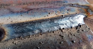
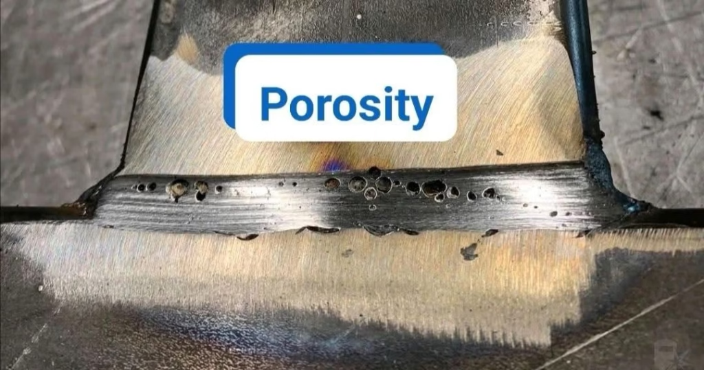
Porosity in welding refers to small, usually spherical or near-spherical gas pockets trapped within the solidifying weld metal. These can be microscopic pinholes or larger cavities; they may be isolated subsurface voids or open to the surface as small pits. Porosity typically results when gas that is soluble or mobile in the molten pool cannot escape before solidification.
What are Blowholes?
Blowholes are generally larger, often irregular cavities in welds or castings formed by the rapid evolution and entrapment of gas. They may appear as visible holes on the surface or as substantial open cavities below the surface. Blowholes are commonly associated with bulk gas accumulation events (for instance, large pockets of hydrogen or trapped atmospheric gas) and often indicate a more severe gas-control or contamination problem than ordinary porosity.

Physical and Metallurgical Differences
Size, Shape, and Morphology
Porosity: tends to be small (pinholes to a few mm), round to ovoid due to surface tension in the molten metal. Microscopic porosity is often spherical.
Blowholes: larger (can be several millimeters to centimeters), irregular or elongated, sometimes with ragged edges when they burst to the surface.
Location (Surface, Subsurface, Through-Thickness)
Porosity can be subsurface or open to the surface; it often distributes throughout the weld bead and heat-affected zone in a scattered pattern.
Blowholes are often surface-breaking or near-surface cavities, and they may be concentrated where gases were trapped by poor gas flow or joint geometry.
Effect on Mechanical Properties
Small, isolated porosity usually reduces ductility, lowers fatigue resistance, and can reduce tensile strength marginally.
Blowholes, because of their size and possible linkage, severely reduce cross-sectional area and act as stress concentrators — greatly affecting tensile and fatigue life and sometimes causing catastrophic failure in pressure-containing parts.
Gas Sources and Formation Mechanisms
Understanding where the gas comes from is key to prevention.
Dissolved Gases and Solubility (Hydrogen, Oxygen, Nitrogen)
Hydrogen is the most common cause of porosity in steels: it dissolves in the molten metal and precipitates as pressure drops during solidification, forming tiny bubbles.
Nitrogen and oxygen also form bubbles; nitrogen can cause embrittlement in specific alloys (e.g., stainless steels), and oxygen can react to form oxides or contribute to gas formation.
Volatile Contaminants and Entrained Gases (Moisture, Oil, Rust)
Moisture (wet electrodes, damp flux, or wet base metal) produces hydrogen when reduced at high temperatures.
Oil, grease, paint, and coatings vaporize and produce bubbles that create porosity or blowholes.
Rust or scale can trap air or release gases during heating.
Process-Special Causes (Flux, Shielding Failure, Splatter, Casting Gases)
In SMAW or FCAW, inadequately dried flux coatings or poor flux composition can release gases.
In GMAW/GTAW, shielding gas contamination (drafts, improperly mixed gas, or leaking hoses) allows atmospheric gases to enter the arc.
In castings, dissolved gases in the melt or gases trapped in the mold can produce large blowholes.
Process-Specific Causes
Shielding Gas Issues (GMAW/GTAW)
Incorrect gas type (e.g., using 100% CO₂ where argon-CO₂ mix is required), low flow rate, drafts, or leaks let air into the arc, causing porosity.
Improper nozzle geometry, long stickout, or damaged contact tips disturb the gas flow pattern and pick up air.
Electrode/Flux Problems (SMAW, FCAW)
Damp or contaminated electrodes and fluxes release hydrogen and other gases.
Improper flux formulation or burned flux can generate large gas volumes—possible blowholes.
Aluminum-Specific Porosity
Aluminum has high hydrogen solubility in the liquid and low solubility in the solid. As it cools, hydrogen leaves the melt forming spherical pores. Common sources: moisture on the surface, oil, or inadequate cleaning of oxides.
Detection, Inspection & Non-Destructive Testing (NDT)
Choosing the proper NDT method depends on whether porosity is surface-connected, its size, and the criticality of the part.
Visual Inspection and Surface Dye Penetrant
Quick and cheap for surface-connected defects. Dye penetrant will not show subsurface porosity.
Use as first-line for cosmetic and small superficial blowholes or pits.
Radiography (X-ray) and CT Scans
X-ray is classic for internal porosity and blowholes: good for spherical and irregular gas cavities. Blowholes show as distinct dark voids on radiographs.
CT scanning gives 3D visualization—best for complex or safety-critical components.
Ultrasonic Testing and Phased Array
UT and phased array can detect internal discontinuities, but gas pockets with rough shapes can reflect weakly; sensitivity depends on equipment and operator skill.
Useful when radiography is impractical (e.g., thick sections not suitable for X-ray).
When to Use Destructive Testing and Metallography
When root cause must be known: cutting a section, polishing and etching, then optical microscopy to examine pore morphology and surrounding microstructure helps identify hydrogen embrittlement, inclusions, or incomplete fusion next to voids.
Acceptance Criteria and Standards
When Porosity is Acceptable vs. Rejection Thresholds
Many industry codes allow limited porosity depending on size, type, and application. For example, minor scattered porosity in non-critical visual welds is often acceptable.
For pressure vessels, aerospace components, or fatigue-critical parts, even small porosity clusters can be cause for rejection.
Critical Applications: Pressure Vessels, Aerospace, Pressure-Tight Welds
In such cases, acceptance is stringent: either very low porosity limits or complete absence of blowholes is required. Always consult the specific code or purchaser’s qualification (AWS, ISO, ASME, EN) for numeric acceptance criteria.
Prevention and Best Practices
Think “clean, dry, controlled” — then repeat.
Joint & Fit-up Considerations
Avoid trapped pockets and blind cavities that can trap gas.
Ensure proper root openings and venting where semi-closed joints exist.
Cleaning, Storage, and Preheat/Drying Procedures
Degrease and remove mill scale, oil, paint, and other coatings.
Bake or store electrodes and flux per manufacturer guidance. Use ovens for low-hydrogen electrodes.
Preheat to drive off moisture in some steels and reduce hydrogen pickup.
Shielding, Travel Technique, and Parameter Control
Maintain correct nozzle-to-work distance and gas flow. Shielding gas must fully envelop the arc and pool.
Use appropriate welding speed and heat input — too fast traps gas; too cold a pool prevents gas escape.
Keep a steady, consistent travel angle and avoid erratic weaving that can trap gas under beads.
Consumable Selection and Handling
Choose low-hydrogen electrodes where hydrogen porosity is a risk.
Use recommended filler materials for aluminum (ER series), and consider special getter alloys or degassing practices when necessary.
Repair and Remediation Techniques
Not every defect requires the same fix.
Grinding Out and Re-Welding
The most common and reliable method. Remove the defect to sound metal, clean the area, and re-weld with correct parameters and consumables.
Peening and Controlled Reheat (Limited Cases)
Peening can close very small, surface-connected porosity in non-critical cosmetic welds, but it is not reliable on internal porosity and can introduce work hardening or cracking risks.
Controlled reheat may allow trapped gas to diffuse, but it’s only useful for specific, low-risk cases and not a replacement for removing large blowholes.
When Rejection Is the Only Correct Action
Where structural integrity is compromised (e.g., large blowholes in pressure-retaining welds), scrap or extensive repair beyond local re-welding may be required.
Root Cause Analysis (RCA) Workflow for Porosity/Blowholes
A structured approach helps avoid repeated failures.
Data Collection and Pattern Recognition
Map where porosity appears: root, cap, toes, specific passes. Is it localized or system-wide?
Record consumable batch, welding parameters, shielding gas batch, environment (cold, humid), and operator.
Systematic Experiments and Controlled Variable Testing
Change one variable at a time (dry electrodes vs. wet, gas flow up vs. down, different travel speeds) to isolate the factor.
Use test coupons under controlled conditions to reproduce the defect before attempting repair on production parts.
Summary Comparison Table (Quick Reference)
| Feature | Porosity | Blowholes |
|---|---|---|
| Typical size | Pinholes to a few mm | Several mm to cm |
| Shape | Spherical/ovoid | Irregular, ragged |
| Typical cause | Dissolved gas (H), slight contamination | Large gas release, trapped air, heavy contamination |
| Typical location | Distributed or subsurface | Surface-breaking or near-surface, localized |
| Mechanical impact | Reduces fatigue & ductility | Severe; can reduce load-bearing section |
| Common fix | Clean + re-weld | Grind out and re-weld; often rejection if large |
FAQs
Can small porosity be left in a structural weld?
It depends on the code and service conditions—small, isolated porosity may be acceptable for non-critical, static-load parts, but not for pressure vessels, fatigue-sensitive, or safety-critical welds. Always check the applicable standard or customer specification.
Which NDT method best distinguishes porosity from blowholes?
Radiography (X-ray) is excellent for visualizing both porosity and blowholes internally. Blowholes typically appear as larger, distinct dark areas; porosity appears as multiple small round spots. CT scanning provides 3D detail if the part and budget allow.
Why does aluminum weld porosity keep happening even with clean surface?
Aluminum absorbs hydrogen readily from moisture and hydrocarbons. Even minute surface contaminants or humidity, or inadequate backing/purge, will produce porosity. Degassing the weld pool (e.g., combining proper cleaning, purge, and controlled heat input) is essential.
Are there quick shop checks to prevent porosity on the day of welding?
Yes—check consumable storage (dry), ensure shielding gas flow and purity, wipe joints with a suitable solvent, confirm ground/clamp contact, and avoid welding in drafts. If using SMAW, check electrode oven temps and storage.
Does peening permanently fix porosity?
No. Peening may temporarily close small surface porosity in non-critical areas, but it does not remove gas trapped below the surface and can introduce other metallurgical issues. It’s not a substitute for proper removal and re-welding in critical applications.
Conclusion
Porosity and blowholes are both gas-related discontinuities but differ in scale, origin, and severity. Porosity is typically the result of dissolved gases like hydrogen forming small spherical voids during solidification. Blowholes are larger cavities formed by the rapid or bulk entrapment of gas or severe contamination. Effective prevention always centers on good housekeeping: clean materials, dry consumables, correct shielding, proper parameters, and thoughtful joint design. Detecting the defects correctly—using visual methods for surface defects and radiography/ultrasonics for subsurface cavities—lets you choose the right repair or rejection action. When in doubt, perform a methodical root-cause analysis: trace the pattern, test one variable at a time, and fix the systemic issue rather than just the symptom.