Ultrasonic Testing (UT) is a non-destructive testing (NDT) technique widely used in the field of welding inspection. It involves the use of high-frequency sound waves to detect and evaluate defects in welds without causing any damage to the tested material.
In the world of welding, NDT plays a crucial role in ensuring the quality and integrity of welds. It helps identify and assess hidden flaws or defects that may compromise the strength, durability, and performance of welded components. By employing NDT techniques such as UT, welding professionals can identify and address these defects early on, preventing potential failures and ensuring the safety of structures and equipment.
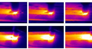
UT is a versatile NDT method commonly employed in welding inspection. It utilizes the principles of ultrasonic wave generation, propagation, and interaction with defects in welds. When an ultrasonic wave is introduced into a material, it travels through it until it encounters a boundary or a defect. At that point, a portion of the wave is reflected back to the transducer, providing valuable information about the presence, size, and location of the defect. By utilizing UT, inspectors can detect various types of welding defects, including inclusions of slag and porosity, lack of fusion and incomplete penetration, cracks, and discontinuities. This allows for thorough examination of welds, ensuring they meet the required quality standards and specifications.
UT offers several advantages in welding inspection. It is a fast and efficient method that provides real-time results, allowing for immediate evaluation of weld quality. It is also non-destructive, meaning it does not harm the tested material, making it ideal for inspecting finished welds and in-service components. Additionally, UT can be automated, enabling high-volume inspections and reducing the dependency on manual labor.
Principles of Ultrasonic Testing
Basics of ultrasonic waves
Ultrasonic waves are high-frequency mechanical vibrations or sound waves with frequencies above the range of human hearing, typically above 20,000 hertz. These waves propagate through materials in the form of longitudinal waves, where particles vibrate in the same direction as the wave’s propagation.
Generation and propagation of ultrasonic waves in materials
Ultrasonic waves are generated using transducers, which convert electrical energy into mechanical vibrations. The transducer consists of a piezoelectric crystal that expands and contracts when an electrical voltage is applied, generating the ultrasonic wave. This wave is then transmitted into the material being tested.
The ultrasonic wave propagates through the material in a straight line until it reaches a boundary or defect. The wave travels at a constant velocity determined by the material’s properties, such as its density and elasticity.
Interaction of ultrasonic waves with defects in welds
When an ultrasonic wave encounters a defect, such as a crack, inclusion, or lack of fusion in a weld, several interactions occur. The waves may be partially reflected, refracted, diffracted, or transmitted, depending on the characteristics of the defect and the material.
Defects cause changes in the path, amplitude, and time of travel of the ultrasonic wave. These changes can be detected and analyzed to determine the presence, size, and location of defects within the weld.
Principles of reflection, refraction, and diffraction in UT
Reflection occurs when an ultrasonic wave encounters a boundary between two materials with different acoustic properties, such as air and a solid. A portion of the wave is reflected back towards the transducer, while the rest continues to propagate through the material.
Refraction happens when an ultrasonic wave passes through a material with varying acoustic properties, causing a change in the direction of propagation. This occurs due to the difference in wave velocity between the two materials.
Diffraction occurs when an ultrasonic wave encounters a small aperture or an obstacle. The wave bends and spreads out beyond the obstacle, allowing the detection of defects that may not be directly in the path of the wave.
By analyzing the reflected, refracted, and diffracted waves, inspectors can gather information about the internal structure and defects within the weld, enabling the identification and assessment of potential issues.
Understanding the principles of ultrasonic wave behavior and its interactions with defects is crucial in effectively utilizing Ultrasonic Testing (UT) for weld inspection. This knowledge forms the foundation for accurate defect detection, sizing, and characterization, enabling the evaluation of weld quality and integrity.
Equipment and Setup
Ultrasonic testing equipment for welding inspection
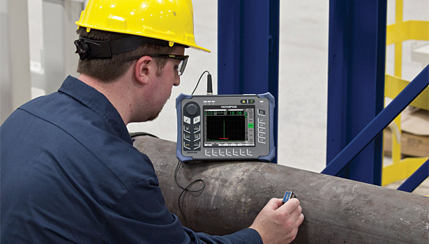
Ultrasonic testing (UT) for welding inspection requires specialized equipment to generate, transmit, receive, and analyze ultrasonic waves. This equipment typically consists of an ultrasonic flaw detector, transducers or probes, a display unit, and data recording capabilities. The flaw detector is the central component that generates electrical pulses, receives and amplifies the reflected signals, and provides visual or numerical representation of the data.
Transducers and probes used in UT
Transducers or probes are crucial components in UT. They convert electrical energy into ultrasonic waves and vice versa. Transducers consist of a piezoelectric crystal that converts electrical energy into mechanical vibrations and vice versa. The selection of transducers depends on the frequency, size, and type of inspection required. Probes are attached to the transducers and come in various shapes and configurations, such as contact or immersion probes, angle probes, and dual-element probes, allowing for versatile inspections in different weld geometries.
Coupling agents and their significance in UT
Coupling agents are substances used to facilitate the transmission of ultrasonic waves between the transducer and the test surface. The purpose of coupling agents is to eliminate the air gap, ensuring optimal contact between the transducer and the material being inspected. Common coupling agents include water, oils, gels, or greases. Their significance lies in maximizing the transfer of ultrasonic energy, minimizing signal loss, and improving the overall accuracy of the inspection.
Calibration and verification of UT equipment
Calibration and verification are critical steps in ensuring the reliability and accuracy of UT equipment. Calibration involves adjusting the equipment’s settings to ensure accurate measurement of signal amplitude, time, and distance. This process is typically performed using calibration blocks or reference standards with known defect sizes and reflector positions.
Verification involves periodic checks to confirm that the equipment is functioning within specified tolerances and meets the required standards. This can include verification of system sensitivity, beam angle, and time-of-flight measurements. Regular calibration and verification of UT equipment are essential to maintain consistency and confidence in the inspection results.
Proper equipment selection, understanding the characteristics and usage of transducers and probes, effective coupling of ultrasonic waves, and regular calibration and verification practices are crucial aspects of setting up UT inspections for welding. By ensuring the appropriate equipment and setup, inspectors can conduct accurate and reliable UT inspections, enhancing the detection and evaluation of defects in welds.
Welding Defects Detected by Ultrasonic Testing
Inclusion of slag and porosity
Ultrasonic Testing (UT) is highly effective in detecting inclusions of slag and porosity within welds. Slag inclusions occur when molten slag gets trapped during the welding process and solidifies within the weld metal. Porosity refers to gas pockets or voids that form within the weld due to the entrapment of gases, such as hydrogen or atmospheric contaminants. UT can identify and evaluate the size, shape, and distribution of these defects, enabling inspectors to assess their impact on the weld’s integrity and mechanical properties.
Lack of fusion and incomplete penetration
UT is capable of detecting lack of fusion and incomplete penetration defects in welds. Lack of fusion occurs when there is insufficient fusion between the weld metal and the base metal or between successive weld passes. Incomplete penetration happens when the weld fails to penetrate the entire thickness of the joint. UT can identify these defects by analyzing the reflected signals and detecting discontinuities at the boundaries where fusion or penetration should have occurred. Evaluating the extent and location of these defects aids in assessing the weld’s structural integrity and strength.
Cracks and discontinuities
Ultrasonic waves are highly sensitive to cracks and discontinuities within welds. Cracks are linear separations in the weld metal or heat-affected zone, which can arise due to factors such as high stress, poor weld quality, or material brittleness. Discontinuities include any abrupt changes or interruptions in the continuity of the weld, such as lack of sidewall fusion or incomplete joint penetration. UT can effectively locate and size these defects by analyzing the reflections, diffracted waves, and mode conversions caused by the presence of cracks and discontinuities.
Undercuts and undercutting
Undercuts refer to grooves or depressions formed along the edges of the weld due to excessive melting or inadequate filler metal deposition. Undercutting occurs when the undercut extends into the base metal, potentially compromising the weld’s strength and load-bearing capacity. UT can detect undercuts by analyzing the reflected waves and identifying the changes in amplitude or time-of-flight caused by the variation in material thickness. Detecting and quantifying undercuts allows for evaluation of the weld’s structural integrity and the need for repair or corrective actions.
Ultrasonic Testing Techniques in Welding Inspection
Pulse-echo technique
The pulse-echo technique is the most commonly used ultrasonic testing technique in welding inspection. In this technique, a single transducer is used to generate ultrasonic pulses that travel through the weld and are then reflected back when they encounter boundaries or defects. The reflected signals are received by the same transducer and displayed on a screen, providing information about the presence, size, and location of defects within the weld.
Time-of-flight diffraction technique
The time-of-flight diffraction (TOFD) technique is a more advanced ultrasonic testing method used for weld inspection. It relies on the diffraction of ultrasonic waves at the tips and edges of defects to provide accurate defect sizing and imaging. TOFD uses two separate transducers, with one transmitting ultrasonic pulses and the other receiving the diffracted signals. By analyzing the time difference between the initial pulse and the diffracted signals, inspectors can precisely measure the size and position of defects, including cracks and lack of fusion.
Phased array ultrasonic testing
Phased array ultrasonic testing (PAUT) is a highly versatile and efficient technique used in welding inspection. It utilizes an array of small transducer elements, each capable of transmitting and receiving ultrasonic waves independently. By controlling the timing and intensity of the individual elements, inspectors can shape and steer the ultrasonic beam, allowing for rapid scanning of complex weld geometries. PAUT provides detailed imaging and accurate defect sizing, enabling inspectors to detect and evaluate various defects, including cracks, lack of fusion, and porosity, with high precision.
Automated UT systems for high-volume welding inspections
Automated ultrasonic testing (AUT) systems have been developed to enhance the efficiency and speed of weld inspection, particularly for high-volume production environments. These systems utilize mechanized or robotic scanners that move along the weld joint, applying UT techniques such as pulse-echo or phased array. AUT systems can be programmed to follow specific scanning patterns and record data automatically. They offer increased productivity, reduced dependency on manual labor, and consistent data collection. AUT is particularly beneficial for repetitive inspections in industries such as pipeline construction, where large volumes of welds need to be inspected efficiently.
Ultrasonic testing techniques, including pulse-echo, TOFD, PAUT, and automated UT systems, provide weld inspectors with a range of options to effectively assess weld quality and detect defects. The choice of technique depends on factors such as the type of defect, weld geometry, inspection requirements, and production environment. Each technique offers unique advantages in terms of accuracy, defect sizing capabilities, and inspection speed, contributing to improved weld integrity and overall quality control in welding processes.
Procedure for Ultrasonic Testing in Welding
Surface preparation and cleaning
Before conducting ultrasonic testing (UT) in welding, proper surface preparation and cleaning are essential. The weld surface should be free from any contaminants, such as oil, grease, paint, or rust, which can interfere with the transmission and reception of ultrasonic waves. Cleaning methods may include wire brushing, grinding, or using solvents to ensure a clean and smooth surface for accurate inspections.
Coupling of transducers to the weld surface
To effectively transmit ultrasonic waves into the weld, proper coupling between the transducers and the weld surface is crucial. A coupling agent, such as water, gel, or oil, is applied to create a thin and uniform layer between the transducer and the surface. This coupling agent helps eliminate air gaps and enhances the transmission of ultrasonic waves, ensuring optimal signal quality and detection of defects.
Scanning and data acquisition
The scanning process involves moving the transducer or the inspection probe along the weld joint while transmitting and receiving ultrasonic signals. The transducer is positioned at specific locations to cover the entire weld volume systematically. The signals received from the reflected, refracted, or diffracted waves are captured by the ultrasonic flaw detector and recorded for further analysis.
Data analysis and interpretation
After data acquisition, the recorded signals are analyzed and interpreted to identify and evaluate any defects within the weld. This analysis involves examining the signal characteristics, such as amplitude, time-of-flight, and waveform shape. Comparisons may be made with reference standards or calibration blocks to determine defect sizes, depths, and positions. Skilled inspectors interpret the data, make decisions regarding the acceptability of the weld, and may provide recommendations for further actions, such as repairs or rework.
The procedure for ultrasonic testing in welding includes surface preparation, proper coupling of transducers, scanning the weld joint, acquiring data, and performing thorough data analysis and interpretation. Following this systematic procedure ensures accurate and reliable detection and evaluation of defects, allowing for informed decisions regarding the quality and integrity of the weld.
Advantages and Limitations of Ultrasonic Testing
Advantages of UT in welding inspection:
- Ultrasonic Testing (UT) is highly sensitive to internal defects within welds, such as cracks, lack of fusion, and porosity. It can accurately detect and size these defects, enabling inspectors to assess the weld’s integrity and make informed decisions regarding its acceptability.
- UT is a non-destructive testing method that does not damage the inspected weld. It provides real-time inspection without the need for destructive sampling, allowing for continuous evaluation and monitoring of weld quality during production or maintenance.
- UT techniques, such as phased array or time-of-flight diffraction, offer the flexibility to inspect complex weld geometries and varying material thicknesses. The ability to shape and steer the ultrasonic beam allows for comprehensive coverage and accurate defect detection in challenging weld configurations.
- UT provides quantitative measurements of defect dimensions, such as length, depth, and width. This information aids in evaluating the severity and criticality of defects and supports decision-making processes for repair or acceptance criteria.
- UT provides immediate results, allowing inspectors to assess the weld quality on the spot. Real-time imaging and display of ultrasonic data facilitate quick and efficient defect identification and characterization.
Limitations and challenges of UT in certain welding scenarios:
- UT requires a clean and accessible surface for effective inspection. If the surface is heavily rusted, rough, or inaccessible due to weld joint geometry or surrounding structures, it may pose challenges in obtaining accurate and reliable results.
- The penetration depth of ultrasonic waves is dependent on the material’s properties and the frequency used. In scenarios where the weld thickness is considerable or the material has high attenuation, UT may have limitations in detecting defects deep within the weld or in the base material.
- Ultrasonic testing requires skilled operators with a thorough understanding of the technique, equipment, and interpretation of results. Proper training and experience are crucial for accurate defect identification, sizing, and characterization, as well as minimizing false calls or overlooking critical defects.
- Surface roughness and certain coatings, such as thick paint or thick corrosion layers, can affect the ultrasonic wave propagation and cause attenuation or signal distortion. Special techniques, such as surface preparation or coating removal, may be required to overcome these challenges.
- UT equipment and specialized techniques, such as phased array or TOFD, can be costly and require skilled personnel to operate and maintain. Initial investment, training, and equipment maintenance can be a consideration for organizations implementing UT in welding inspection.
Understanding the advantages and limitations of ultrasonic testing in welding inspection allows for informed decision-making regarding its applicability, effectiveness, and potential challenges in different scenarios. Despite the limitations, UT remains a valuable and widely used non-destructive testing technique for weld quality assessment, defect detection, and ensuring structural integrity.
Real-Life Applications
Examples of UT applications In Welding
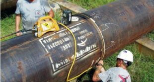
- Pipeline weld inspections: Ultrasonic Testing (UT) is extensively used in the oil and gas industry for inspecting welds in pipelines. It enables the detection and characterization of defects such as lack of fusion, cracks, and porosity, ensuring the integrity and safety of the pipeline infrastructure.
- Pressure vessel inspections: UT plays a critical role in assessing the quality and reliability of welds in pressure vessels used in various industries, including chemical plants and power generation. It helps identify defects such as inclusions, lack of fusion, and cracks, ensuring the structural integrity and preventing potential failures.
- Structural steel inspections: In the construction industry, UT is utilized for inspecting welds in structural steel components, such as bridges and buildings. It helps identify defects that can compromise the load-bearing capacity and durability of the structures, allowing for timely repairs or replacements.
- Aerospace industry applications: UT is widely employed in the aerospace industry to inspect welds in critical components, such as aircraft engine parts and fuel tanks. It ensures the quality and reliability of these welds, preventing potential failures and ensuring the safety of air travel.
FAQs
What is ultrasonic testing for weld inspection?
Ultrasonic testing for weld inspection is a non-destructive testing technique that utilizes high-frequency sound waves to detect and characterize defects within welds. It is used to assess the quality, integrity, and structural soundness of welds in various industries.
What is ultrasonic inspection techniques in UT?
Ultrasonic inspection techniques in UT involve the use of transducers that emit high-frequency sound waves into the weld material. These waves travel through the material and are reflected or diffracted when encountering defects. By analyzing the reflected waves, defects such as cracks, lack of fusion, or porosity can be detected and evaluated.
What is NDT ultrasonic testing?
NDT ultrasonic testing is a non-destructive testing method that uses ultrasonic waves to assess the integrity and quality of materials, including welds. It involves the generation, propagation, and analysis of ultrasonic waves to identify and characterize defects or anomalies within the material being inspected.
What is the UT standard for welding?
The UT standard for welding may vary depending on the specific industry or application. However, commonly referenced standards include those from organizations such as the American Society for Nondestructive Testing (ASNT) and the American Welding Society (AWS). International standards such as ISO 17640 are also widely recognized for UT in welding inspections.
How is ultrasound used in welding?
Ultrasound is used in welding as a non-destructive testing method to detect defects and ensure the quality of welds. Ultrasonic waves are directed into the weld material, and the echoes or reflections of these waves are analyzed to identify and characterize defects, such as cracks, inclusions, or lack of fusion.
What is the ASME code for ultrasonic testing?
The ASME (American Society of Mechanical Engineers) Boiler and Pressure Vessel Code Section V provides guidelines and requirements for ultrasonic testing in welding inspections. It outlines the procedures, acceptance criteria, and qualifications for personnel performing ultrasonic testing in accordance with ASME standards.
What is the UT welding test procedure?
The UT welding test procedure refers to the specific set of instructions and guidelines for performing ultrasonic testing on welds. It includes details on equipment setup, calibration, scanning techniques, data acquisition, and data analysis to ensure consistent and reliable results in weld inspection.
What is the advantage of ultrasound NDT?
The advantage of ultrasound NDT is its high sensitivity to internal defects within welds. Ultrasonic testing can accurately detect and size defects such as cracks, lack of fusion, or porosity. It provides quantitative defect sizing, immediate results, and real-time imaging, enabling informed decision-making regarding the weld’s acceptability and ensuring structural integrity.
What is ultrasonic test for steel?
Ultrasonic testing for steel is a non-destructive testing method used to assess the quality and integrity of steel materials, including welds. It involves the use of ultrasonic waves to detect and characterize defects, such as inclusions, cracks, or lack of fusion, within the steel material. This helps ensure the reliability and safety of steel structures and components.
Conclusion
In conclusion, Ultrasonic Testing (UT) is a crucial non-destructive testing (NDT) technique used for inspecting welds in various industries. It offers numerous advantages, including high sensitivity to internal defects, non-destructive nature, versatility in weld geometry, and quantitative defect sizing. UT plays a vital role in ensuring weld quality, integrity, and the safety of structures and equipment.
Although UT has limitations and challenges, such as surface condition constraints, limited penetration depth, operator skill requirements, and equipment costs, ongoing advancements in technology and techniques are addressing these issues. Future trends and developments in UT are focused on improving inspection capabilities, enhancing automation and data analysis, and reducing inspection time and costs.
Training and certification requirements for UT technicians, standardization and codes governing UT, and regular maintenance and calibration of equipment are essential best practices for effective UT in welding inspections. Compliance with industry standards and adherence to recommended procedures are crucial to ensure reliable and accurate results.
Looking ahead, the future of UT in welding inspections is promising. Advancements in equipment, such as more advanced phased array and TOFD systems, are providing enhanced inspection capabilities. Automation and robotics are playing a significant role in streamlining UT inspections, increasing efficiency, and reducing human error. Additionally, developments in data analysis techniques, including artificial intelligence and machine learning, are enabling more accurate defect characterization and predictive analytics.
As technology continues to evolve, it is important for practitioners to stay updated with the latest advancements, regulations, and best practices in UT. The effective implementation of UT in welding inspections will contribute to improved weld quality, extended service life of structures, enhanced safety, and compliance with industry standards.