What Causes Welding Spatter?
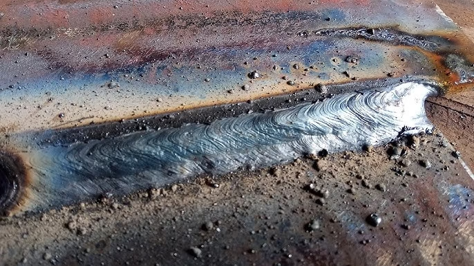
Welding spatter is caused by unstable molten metal droplets being ejected from the arc or weld pool. The instability arises from a combination of incorrect process parameters, consumable or base-metal contamination, poor shielding or gas flow, equipment faults, and operator technique.
Fundamental physics of arc metal transfer
Melt pool dynamics and droplet formation
At its core, spatter is a droplet of molten metal produced by the arc that does not join the weld pool smoothly. The arc melts filler and base metal; the molten metal forms droplets that transfer across the arc gap under the influence of forces. Ideal transfer deposits droplets predictably into the pool — undesirable transfer ejects droplets outward.
Role of surface tension, electromagnetic forces, and gas flow
Three main forces determine whether a droplet joins the pool or becomes spatter:
Surface tension tends to hold the droplet together and keeps the metal attached to the wire or pool.
Electromagnetic forces (pinch effect) created by welding current can cause droplets to detach; higher currents increase these forces.
Plasma and shielding gas flow exert drag on the droplet; turbulent flow or incorrect gas mixtures can push droplets away.
Process-specific causes
GMAW/MIG — short-circuit, globular, spray transfer
MIG welding can operate in several transfer modes:
Short-circuiting transfer (low current): The wire contacts the pool and shorts, then melts and detaches. If voltage or timing is off, or if the wire stick-out is wrong, the short can be violent and throw spatter.
Globular transfer: Large, irregular droplets fall from the wire in an uncontrolled way — inherently spattery because droplets are bigger than the arc diameter and have unstable trajectories.
Spray transfer: Fine droplets are sprayed across the arc. When set correctly, spray transfer is the cleanest for output and minimizes spatter; wrong current or gas mix can push it toward globular behavior.
FCAW — flux effects and self-shielding behavior
Flux-cored wires produce gases and slag from their flux. FCAW-S (self-shielded) often runs spattery when the flux chemistry, wire speed, or current cause unstable transfer or excessive slag ejection. Contaminated flux or wrong wire diameter worsens spatter.
SMAW (Stick) — slag and arc instability
Stick welding produces slag that covers deposited metal. Spatter in SMAW is commonly due to excessive current, poor electrode manipulation, or arc length deviation; the electrode flux composition also influences the arc’s aggressiveness and tendency to eject droplets.
GTAW/TIG — when spatter can still occur
TIG is the cleanest, but spatter can still appear if filler addition technique is poor ( dipping the rod into the arc causing splatter), if tungsten contaminates the puddle, or if shielding gas turbulence disturbs the arc. In automated TIG, gas flow and torch alignment can be culprits.
Welding parameters that generate spatter
Excessive current/voltage and arc energy
Too much current increases the electromagnetic pinch and causes larger droplets to be expelled. Notably in spray or globular modes, small increases in current can shift transfer mode and suddenly raise spatter.
Incorrect wire feed speed, stick-out and contact tip issues
Wire feed speed and corresponding voltage must be matched; too high feed produces oversized droplets; too low feed results in burnback and erratic shorting. Excessive stick-out reduces the welding current density near the contact tip, increasing arc instability and spatter.
Travel speed, arc length, and torch angle
Long arc length increases the arc’s energy and expands droplet formation zones — more spatter.
Slow travel speed can allow the puddle to bulge and eject droplets.
Incorrect torch angle (too steep or off-axis) deflects droplets from their intended path.
Polarity and waveform effects (DCEN, DCEP, pulsed)
Polarity affects heat distribution and metal transfer. For many wires, DCEP produces a stronger pinch and cleaner transfer in spray mode. Pulsed MIG allows control over droplet detachment by cycling current; when set well, pulsed waveforms significantly reduce spatter compared with constant current.
Consumables, materials, and contamination
Filler wire chemistry and diameter
Wire diameter changes the droplet size: larger diameters tend to produce larger droplets, increasing spatter risk in certain transfer modes. Wire chemistry affects fluidity and surface tension — e.g., silicon and manganese content change wetting behavior.
Base metal condition: rust, oil, paint, plating
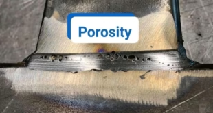
Contaminants on the base metal create localized boiling and gas evolution at the weld pool; when pockets of gas pop out they can eject molten metal as spatter. Oil, grease, paint, zinc (galvanizing), and rust are common culprits. For instance, welding over zinc can vaporize the coating and create violent droplet ejection and porosity.
Flux, coatings, and surface contaminants
Flux in FCAW or flux on stick electrodes, when compromised by moisture or improper storage, can produce uneven gas evolution and increase spatter. Coatings with volatile elements (e.g., cadmium, water in flux) also cause instability.
Shielding gas and external environment
Wrong gas mix or flow rate
Shielding gas composition strongly influences transfer mode. Pure CO₂ tends to promote globular transfer and more spatter at higher currents, while argon-rich mixes encourage spray transfer with finer droplets. Too low gas flow fails to protect the arc and creates turbulence; too high flow causes turbulence and entrainment of air, both increasing spatter.
Air drafts, wind, and draft control
Drafts disturb the shielding envelope and the arc, causing unstable transfer. Outdoor or poorly ventilated setups without wind control will see higher spatter rates.
Equipment condition and maintenance
Nozzle, contact tip, liner and cable issues
Build-up of spatter on the gas nozzle changes flow patterns. A clogged nozzle creates turbulence and may divert shielding gas away from the arc. Worn contact tips or contaminated liners lead to poor wire feeding and erratic electrical contact — both sources of spatter.
Grounding, connections, and machine calibration
Poor ground connections create unstable arcs and current fluctuations. Miscalibrated power sources supplying inconsistent current or faulty wire feeders that stutter will directly cause spatter episodes.
Operator technique and human factors
Poor torch manipulation and operator habits
Incorrect travel speed, inconsistent stick-out, poor rod dipping (TIG), or jerky motions produce transient arc instabilities leading to spatter. Human habits such as pressing into the puddle or swinging the torch increase ejection.
Training, fatigue, and ergonomics
Tired welders or those lacking training are more likely to run improper parameters and make inconsistent welds, raising spatter. Good work ergonomics facilitate steady hand movement and consistent arc control.
How to diagnose spatter causes
Stepwise diagnostic flow
Visual check of base metal — remove rust, paint, oil.
Inspect consumables — fresh wire, correct diameter, clean tip.
Examine gas — correct mix and adequate flow; watch for drafts.
Check equipment — nozzle clean, tip tight, liner smooth, ground secure.
Review parameters — wire feed, voltage, current, travel speed, stick-out.
Observe operator technique — angle, speed, arc length consistency.
Run controlled tests — change one variable at a time to isolate the cause.
Quick tests to isolate variables
Swap shielding gas for a known good mix to see if spatter drops.
Lower current in small increments to find a stability window.
Clean the part and touch off a short bead; if spatter reduces, contamination was likely.
Replace contact tip and run a short bead to see if wire feeding was the issue.
Preventive strategies and best practices
Parameter tuning and transfer mode selection
Choose the proper transfer mode for the material and position: short-circuit for thin sections, spray or pulsed spray for thicker work.
Match wire feed speed and voltage curves recommended by wire manufacturers and machine vendors.
Use pulsed MIG where possible to control heat input and reduce spatter.
Consumable selection and pre-cleaning
Use the right wire chemistry and diameter for the job.
Pre-clean base metal thoroughly; degrease, remove rust, and avoid welding over thick coatings unless properly prepared.
Store flux and electrodes dry and at recommended conditions.
Equipment maintenance and gas handling
Keep nozzles and tips clean; replace worn parts promptly.
Use proper liners and feed systems; verify correct spool tension and guide path.
Set gas flow to manufacturer-recommended rates and protect the weld area from drafts.
Process improvements: pulsed MIG, servo feeders, anti-spatter
Pulsed MIG reduces droplet size and gives better control over transfer, dramatically decreasing spatter in many situations.
Servo feeders provide smoother, more accurate wire feed than low-quality gear motors.
Use anti-spatter sprays or gels sparingly and correctly — they help cleanup but do not replace proper parameter control and technique.
Post-weld spatter removal and inspection
Mechanical removal: chipping, brushing, grinding
Common methods include wire brushing, chipping with a hammer (for stick weld slag), and grinding for stubborn droplets. Choose the method that preserves the parent metal and the bead profile.
Chemical and anti-spatter agents
Chemical anti-spatter agents make removal easier by preventing adhesion; solvents dissolve certain splatters but must be used with safety precautions and compatibility checks (avoid reactions with coatings).
Inspection criteria and acceptance
Assess whether spatter affects weld integrity (undercut, lack of fusion, porosity) or just appearance. Inspection standards may allow cosmetic spatter up to certain limits; critical or cosmetic parts often require near-zero spatter.
FAQs
Which welding process produces the least spatter?
GTAW (TIG) typically produces the least spatter.
Will anti-spatter spray remove the need to adjust parameters?
No. Anti-spatter spray helps cleanup but does not replace proper parameter tuning.
How does shielding gas composition affect spatter?
Gas mix influences transfer mode — argon-rich mixes favor spray transfer (less spatter), while CO₂ tends toward globular transfer (more spatter).
Is spatter harmful to weld strength?
Usually spatter is cosmetic, but heavy spatter can indicate unstable welding that may correlate with defects affecting strength.
Conclusion
Welding spatter is a multi-factor problem — not a single villain. It emerges when the physical balance of forces at the arc and the weld pool is disrupted by inappropriate settings, contaminated materials, faulty equipment, environmental disturbances, or inconsistent operator technique. The good news is that nearly every cause is addressable: thoughtful parameter selection, proper consumables, routine equipment maintenance, controlled gas shielding, and operator training will dramatically reduce spatter. Treat spatter as an early symptom; a systematic troubleshooting approach fixes the root cause rather than simply cleaning up the mess. Like tuning a musical instrument, achieving low-spatter welding requires small, deliberate adjustments until the arc sings in tune.